Introduction
I have a couple of these radios in excellent working order. The first one was "loaned" to me by Derek, VK2DRK, and I was so impressed I went out and sourced another. Derek's radio at the time had the 6 channel EPROMs already programmed for the local 2Meter repeaters and digital mode use.
No repair or alignment work was required on this radio, which is just as well because I didn't have a schematic diagram or service manual.
I immediately started hitting Google for some info on this radio. Not much was found. I did work out that there is a commercially available programmer (KT-90?) for this radio, and that I could send it away and get 6 new channels programmed for $US40.
I don't think so...
The radio was very usable in it's current form but I still couldn't resist the temptation to open it and have a look. What I found was that this radio was potentially capable of a lot more than the 6 Channels provided by the channel selector switch and PROMS.
Uncovering the underbelly of the radio reveals the Motorola MC145152 PLL chip and the two M54730AP PROMS. This is where most of the action is going to be performed, as we will remove the PROMS and interface directly with the PLL chip.
PLL Chip - MC145152
This chip is a bit more advanced than the other PLL chips that I worked with as a kid ;-). Everyone remembers the classic PLL-02A, where 9 bits were used in the make up of the divide-by-N-codes for PLL programming.
If you know how to do binary programming on the old PLL-02A (and understand things like N-Codes), you won't have any problems here.
This chip has N-codes and A-codes. This concerned (Confused?) me for a while, and I even asked around on the local 2 meter band for advice. No one I spoke to knew what an A-Code was, and in the end it didn't matter much anyway, as I found that you can just assume that the programming is strait 16 bit, and treat the A-codes like the lower 6 bits of an N-Code word.
Motorola provide datasheets on their website, but even so I have provided the pinouts below.
The MC-14152 is described by Motorola as a 16 bit parallel input N/A counter with a three input R counter. This sort of detailed information might not even matter to you. The radio that I have was already set up for 5kHz channel spacing, all I had to do was reverse-engineer the appropriate N-Codes. A0 is the Least Significant Bit (LSB) and N9 is the Most Significant Bit (MSB).
There are 6 A codes (A0-A5) and 10 N Codes (N0 - N9), which give you 2^16 (65536) channel spacings.
The chip is a 28 pin device found under the radio, next to the OFF/VOL switch/POT.
Below is the pin assignments for the MC145152 PLL chip:-
|
1 |
F-in |
28 |
LD |
|---|---|---|---|
|
2 |
VSS |
27 |
OSC-in |
|
3 |
VDD |
26 |
OSC-out |
|
4 |
RA0 |
25 |
A4 |
|
5 |
RA1 |
24 |
A3 |
|
6 |
RA2 |
23 |
A0 |
|
7 |
0R (phase det 'B' out) |
22 |
A2 |
|
8 |
0V (phase det 'B' out) |
21 |
A1 |
|
9 |
MC |
20 |
N9 |
|
10 |
A5 |
19 |
N8 |
|
11 |
N0 |
18 |
N7 |
|
12 |
N1 |
17 |
N6 |
|
13 |
N2 |
16 |
N5 |
|
14 |
N3 |
15 |
N4 |
The next thing that you will need to know is the pinouts for the EPROM sockets. It was a quick check with the multimeter to determine the connection points of interest, but here it is to save you a bit of time.
|
|
|
M1 socket |
|
|
|
M2 Socket |
|
|
|---|---|---|---|---|---|---|---|---|
|
1 |
A0 |
16 |
VCC |
|
1 |
N2 |
16 |
VCC |
|
2 |
A1 |
15 |
|
|
2 |
N3 |
15 |
|
|
3 |
A2 |
14 |
PTT |
|
3 |
N4 |
14 |
PTT |
|
4 |
A3 |
13 |
|
|
4 |
N5 |
13 |
|
|
5 |
A4 |
12 |
|
|
5 |
N6 |
12 |
|
|
6 |
A5 |
11 |
|
|
6 |
N7 |
11 |
|
|
7 |
N0 |
10 |
|
|
7 |
N8 |
10 |
|
|
8 |
Gnd |
9 |
N1 |
|
8 |
Gnd |
9 |
N9 |
All the logic signals you need come through these sockets, including the PTT (Push To Talk) line , which is required if you want to do repeater offsets.
The only line that I would find handy that is missing here is an indication when the squelch was open. This could make developing a scanning system easier. This signal would be available elsewhere in the radio.
The radio doesn't care that the two PROMs are removed, as long as they are replaced by something that talks the right language.
Enter PICAXE and 74595 chips!
I don't intend to make this a step-by-step tutorial on building a PLL controlling system for this radio (although I will gladly give away my source code and diagrams for free). My intention is to give ideas on what can be done.
I chose to use PICAXE devices because they have built-in serial commands, they can be programmed and debugged in-circuit and you can move from the low-end devices to the more capable devices without changing your development environment. They are programmed in a simple "BASIC" language dialect. It is true that you loose a bit of the raw capability of the underlying PIC platform when you buy them as PICAXE, but the development, debugging turn around times and ease of use means that I am not likely to go back to vanilla microchip devices anytime soon.
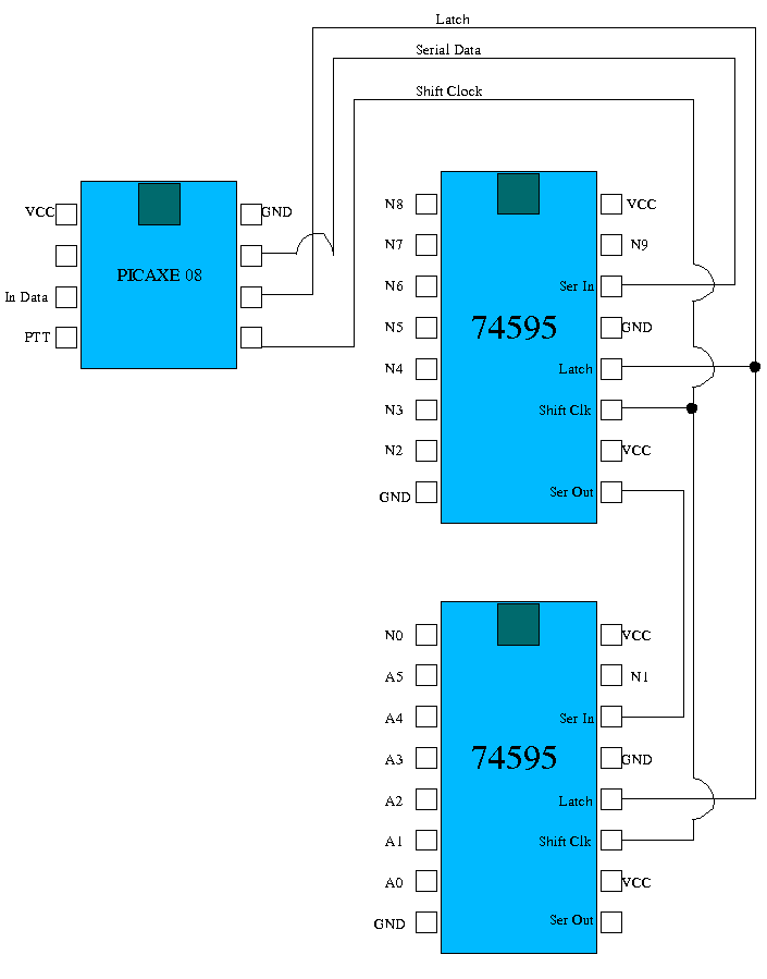
The heart of the system is the PLL controller circuit. It consists of a PICAXE 08 microcontroller and two 74595 serial to parallel converters. The 74595 devices provide output port expansion for the PICAXE 08 and two of them are required to control 16 bits.
Other than shifting for repeater use on PTT signal, my PLL controller circuit doesn't decide on the N-Codes that should be used. All it does is listen for the instructions on what to do on a serial port. These instructions could come from a computer, or in my case a separate box that allows you to select the required frequency. I intend to write a small Java application for controlling the radio with a PC (or any machine with a JVM, like a Pocket PC) and will make it available here.
PLL Controller Diagram and source code.
; PLL_Controller.bas. Used in a PICAXE-08
Symbol clock = 2
Symbol dataout = 0
Symbol latch = 1
Symbol PTT = pin3
Symbol TXFreq = W5
Symbol RXFreq = W3
Symbol InFreq =
pin4
; Final N Code is (freq_in_Khz/5) - 4280
; or N Code
is (drop the leading "14") e.g. 6950=146950
; N=
(Last_4_Digits_Of_Freq/5)+23720
; e.g. N=(6950/5)+23720 for
146950
; In my radio 144000 MHz Ncode is 24520
; In my radio
148000 MHz Ncode is 25320
;TXFreq = 24990
;RXFreq =
25110
;RXFreq = 4800/5+23720
;TXFreq = 6950/5+23720
pause
50
main:
if InFreq = 1 then ReadNewFreq
if PTT = 0 then
SetRXFreq
if PTT = 1 then SetTXFreq
goto main
NewFreq:
for b0 = 0 to 15
let b1 = W2&1
if b1 = 1 then HighBit
low dataout
goto ClockOut
HighBit:
high dataout
ClockOut:
pulsout clock,2
let w2=w2/2
next b0
pulsout latch,2
goto main
SetRXFreq:
W2 =
RXFreq;/5+23720
goto NewFreq
SetTXFreq:
W2 =
TXFreq;/5+23720
goto NewFreq
; Now we have to read in the
new freq somehow.
ReadNewFreq:
if pin4 = 1 then ReadNewFreq ;
Wait for the start
serin 4,N2400,b6,b7,b8 ; b8 is the offset
signal, b6+b7=w3(RxFreq)
RXFreq = RXFreq/5+23720
if b8 = 0
then noOffset
if b8 = 1 then downOffset
if b8 = 2 then
upOffset
goto main
noOffset:
TXFreq = RXFreq
goto
main
downOffset:
TXFreq = RXFreq-120
goto main
upOffset:
TXFreq = RXFreq+120
goto main
Code description.
The PICAXE-08 does not support interrupts and as the serin command blocks code execution until valid serial data is received, I needed to find a way to signal when a new N-Code was being sent to the PLL Controller. I did this by checking if the data input pin (InFreq) has been held at logic 1. When I see this pin at logic 1, I jump to the ReadNewFreq procedure. ReadNewFreq then waits for the InFreq pin to go low. After a low is read on InFreq, the program waits for serial data using the serin command. The software sending this data must be written to signal that a new N-Code is being sent in this way.
Repeater offsets are handled by a flag set in B8 (Byte 8). I do not handle arbitrary offsets in this code (i.e. it is fixed at 600khz), however it would be easy to modify it to do so if required. If B8=0 then TXFreq = RXFreq (simplex), IF B8=1 then TXFreq is 600Khz below RXFReq (N-120), and if B8=2 then TXFreq is above RXFreq (N+120).
Loading the serial data into the two 74595's is done by "logically and-ing" the least significant digit of W2. If the result of this operation is "1", then I put a high state on the dataout pin, if the result is "0", I keep the dataout pin low.
Frequency selection (or n-code generation).
There are a few options here.
The first option you have is to simply add this circuit to replace the existing PROM with your own channels. You could use the existing channel selector or add your own up/down channel switch. It could be a cheaper option than paying someone to burn some new proms, and would be reprogramable very quickly. The complete setup including a couple of PICAXE '08s and everything you need to start programming them is probably only a few dollars away for most people with a PC. This was my original goal when starting this project.
If you would rather "cut code" than smell solder fumes, you could just build a minimal PLL controller and permanently connect the PLL controller to a PC. Write some software to send the controller the required n-codes, give it a nice user interface and you could have a very capable radio with scanning, memories and all the things that you expect from a modern radio. Write your software on a Palm Pilot or a Pocket PC device and you have a very capable mobile unit. This would be be easy as long as you remember to hold the inFreq ping high for a few hundred milliseconds before sending your serial data.
Another option is to build your own bit of hardware that talks to the PLL controller directly. This could give you some of the features of sticking a full blown PC on top of the radio, but is cheaper and keeps the radio useful as a mobile unit.
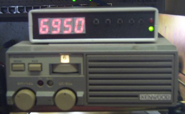
At the time of receiving this radio, I was lacking a quality unit that could cover the whole 2M band for mobile use. After verifying the operation of the PLL controller and a quick check of my junk box for inspiration, I decided to build a simple box with a frequency display and repeater offset buttons. I won't detail the frequency selection unit here, as being built from junk-box bits, it's not really a "best-of-breed" design, but I am happy to discuss what I did via email. See below for a picture.
Acknowledgments:
Derek, VK2DRK, for giving me the opportunity to have a play with this radio - Thanks.
Watts Communications, ACT. Friendly guys who let me look at the service manual.
Silicon Chip Magazine for the idea on PICAXE port expansion (i.e. The use of the 74595 shift registers). Everyone in Australia should support this magazine.