CONTACTOR UNIT BC-608-A
|
VK2DYM'S RADIO AND RADAR INFORMATION. |
RADIO IDENTIFICATION SYSTEMS – IDENTIFICATION, FRIEND or FOE or I.F.F.
From the time that there was more than one living entity on this earth there has been a requirement for one to identify the other as friendly or hostile. This very important need was considered at the same time as radar was being developed in various countries, prior to WW2. The system that evolved was known as Identification, Friend or Foe or IFF and in the first instances in both UK and USA it consisted of a simple dipole mounted on the friendly vehicle, resonant to the radar frequency, and switched open or shorted, so that it produced a fluctuating radar echo as an identifying characteristic. The main beneficiary of IFF was the air force but land and sea units were also fitted out. The first trials were made with a British Heyford Bomber which was of wooden construction and the wire IFF antenna was just attached across the wings. This simple system suffered from lack of distance, unacceptable variability and could only respond to one frequency. In short, it didn't work.
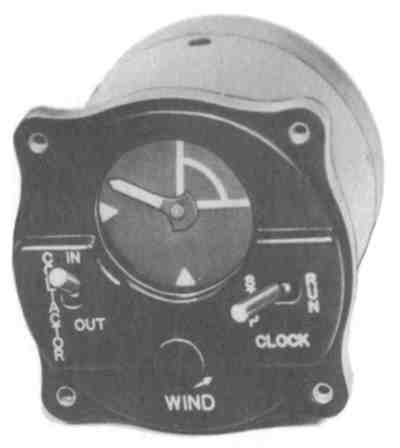
PIPSQUEAK. Another early attempt at identifying friendly aircraft was known as "Pipsqueak". In this system, developed in UK but used by the allies and designated in the US as RC-96A, a clock was fitted in the cockpit, either in the instrument panel or on an added bracket. This clock had a hand that rotated once every minute. Internally, a switch operated for a period of 14 seconds, starting at the 12 o'clock position. In turn, the switch actuated the aircraft transmitter so that Direction Finding stations could get a rough idea of the aircraft's location and determine that it was friendly. The clock was called the Contactor Unit BC-608*, as shown below.
CONTACTOR UNIT BC-608-A
The clock was mechanical and hand wound, preferably every 12 hours, although it could run for 24 hours. In operation, the pilot would actuate the clock STOP-RUN switch before take off. Thereafter the aircraft transmitter would be actuated to send out an unmodulated signal for about 14 seconds of every minute, ie. in the 12 o'clock to 3 o'clock quadrant indicated. The transmitter switching could be disabled by the contactor IN-OUT switch, leaving the clock to continue running.
When the contactor was in operation it meant that the pilot could not use his transmitter or receiver during that 14 seconds, or if he was in the middle of transmission when the contactor came to it's 12 o'clock position, he would be cut off.
This system was fitted mostly to fighter aircraft and interconnected to the common SCR-274 (Command) sets in US aircraft and the TR9 in UK fighters. Later the Contactor was fitted to the VHF SCR-522 sets as they were introduced in aircraft. Here position D on the 4 position push button channel switch was used for DF. A relay in the SCR-522 transmitter caused a 1000 cps tone in the headphones so the pilot knew when pipsqueak was operating.
In practice, it is doubtful whether it fulfilled it's intended purpose of identifying the location of friendly aircraft and it was probably a pain for the pilots, having to watch that clock before transmitting a message.
IFF Mark I, developed by 1939, was an improvement on the passive dipole and Pipsqueak, consisting of a receiver/transmitter carried in the unit that was to be identified. The IFF set was normally in receive mode but when energised by a radar signal, it broke into oscillation and became a transmitter. The return signal mixed with the radar return to provide a distorted and identifiable echo. The tuning of the IFF set was mechanically swept across the band of frequencies covered by the radars in use so each radar would receive a response when the receiver matched the radar's frequency. At this time the predominant UK CH radars operated at frequencies between 20-30 Mhz.
IFF Mark II was developed to cope with the additional frequency bands of newer radars, and covered these in three swept ranges, including the original IFF MK I band. However, radars were advancing at such a rate that IFF MK II soon did not cover the frequencies in use so variations were produced for other radar bands, such as the IFF MK IIG and MK IIN which were British sets for UK radars, and the USA SCR-535 (ABE) and SCR-535-A which worked with the early US Army radars such as the SCR-268, SCR-270, SCR-271 and SCR-516. The US Navy ABE and ABK sets worked with naval radars.
The IFF MK II was designed to allow switching between any one of 6 different coded responses, usually specified for various types of mission. However, in practice it proved difficult to distinguish one echo from another so generally only position 1 (or A) was used, whilst the longest, widest response position was used universally as a distress signal.
In order to respond to the growing number of radars in service the aircraft or ship often had to carry multiple IFF units. The services recognised that with the proliferation of radar and other equipment there was a need for a distinct frequency band for IFF with a common equipment specification. They chose the 157-187 Mhz band.
IFF MK III. This was a standardised system used by the Allies, where IFF MK III refers to the complete system including the transmitter, receiver, control boxes, coding units etc. The components of IFF MK III included:-
Interrogator. This was a radio transmitter located close to the ground radar set and interfaced with it to transmit between radar pulses.
Responsor. This was a receiver also attached to the radar set (usually in the same box as the Interrogator) and it received the return identifying signal and processed it for display on the radar screen. It was automatically switched so that it was not overloaded by the radar pulses.

SCR-602 radar. The IFF Interrogator/Responsor is the BC-800-B that can be
seen
at top right next to the cooling fan. It interfaced with the "A"
Display directly below.
Transponder. This was a combined Receiver/Transmitter fitted to the unit (aircraft, ship, etc) which needed to be identified. Upon receipt of an interrogating signal it responded with a coded signal on the same frequency. The coding could be switched in form and duration for specific missions. The original British IFF MK III transponder (R3090) was copied in the USA for their navy as the ABK and some of these were used by the US Signal Corps as the SCR-595. The US Army had a large number of SCR-695's, similar to the British IFF MK IIIG (R3121). Note that to confuse the enemy the Transponders were given receiver nomenclature, eg UK used "Rxxxx" and the US used "Radio Set, SCR-xxx". (I’m sure that kept the enemy guessing as to what they were!)
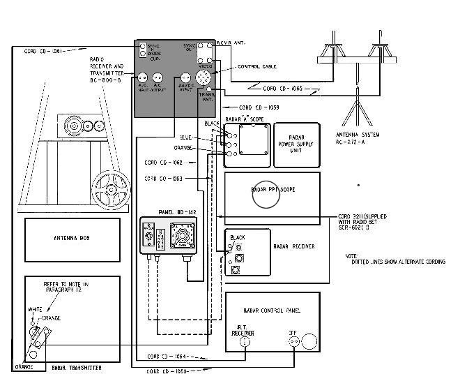
Layout of components of SCR-602-T6 showing position of BC-800 and Control Box
BD-142.
The receiver tuning of the IFF MK III transponder was swept across a limited band of frequencies allocated for the purpose, whilst the Interrogators were set on spot frequencies within the range. This overcame to a large extent the problems of mutual interference and multiple responses to numbers of radars in any one area. In addition the interrogator only needed to be pulsed when needed, to get a response from an unknown radar blip. This was better than having the transponder being activated all the time by the primary radar, which would have meant that there were continuous replies from the transponders (and that would have been of great interest to the enemy).

The top Trace shows two unidentified echoes. The lower Trace shows what happens when the
first plane transmits it's IFF signal, which deflects the Trace downwards, in response to an
interrogating pulse.
In the simplest case the IFF return was arranged to give a negative deflection on the radar range screen (the "A" Display), coinciding with the positive radar echo. This was the set up on the SCR-602 series radars. In more complex systems the IFF return was shown as a separate trace on the screen, as with the SCR-268 or on a separate range CRO display, as in the SCR-588. Because the active transponder signal was generally stronger than the radar echo, it often showed up well before the main radar echo, as illustrated below.
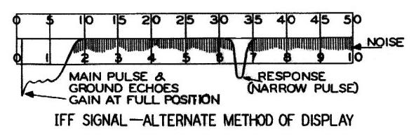
A typical downwards IFF responsor trace showing a friendly vehicle at 33
miles, even though the radar hasn't picked it up yet.
When used with Ground Controlled Interception (GCI) radar such as the US SCR-588, SCR-527 and SCR-627 which had a PPI display and where there were likely to be many responses, the interceptors were fitted with the Radio Set SCR-695 (IFF MK IIIG) which had a special switched circuit that covered the GCI control frequency. It pulsed a response at about 5 cycles per second and was shown on the main PPI display at the same position as the radar echo.
Coding.
The Transponder swept across the range of IFF frequencies in about 2 1/2 seconds
by way of a motor driven variable capacitor. Coding was accomplished by a
rotating disk with notches actuating a microswitch and could be set for a) No
reply, b) a narrow pulse and c) a wide pulse. A Coding cycle consisted of 4
sweeps of the band after which the sequence repeated, with a possible 6 distinct
codes selected by a control box in the cockpit etc with a switch marked A to F.
The entire cycle took about 10 seconds. There was another switch, located near
the pilot in an aircraft, which produced a very wide pulse and was used as a
distress signal.
US Army Air Force IFF MK III Equipment.
The US Army Air Forces used two types of IFF MK
III,
a) Radio
Set SCR-595 which was actually a Navy set, the ABK. It was the US version of the
British IFF MK III Transponder (R3090) and was mechanically and electrically
interchangeable. It was fitted to bombers and transports, but not to fighters,
which generally came under GCI control.
b) Radio Set SCR-695 which was an American built set used by the US Army Air Forces, the US Navy as well as the RAF and was similar to the British IFF MK IIIG (R3121). It could be installed in any aircraft because it had the additional fixed frequency response for GCI action.
The US built a number of different models of Interrogator/Responsor to cover the different operating spot frequencies associated with each type of radar. They consisted of a Transmitter, a Receiver, an interconnect unit to interface to the specific radar, an antenna system and in some cases a display unit. These were:-
| RC-127 for SCR-527 radar | RC-184 for SCR-584 radar |
| RC-136 for SCR-296 radar | RC-188 for SCR-588 radar |
| RC-145 for SCR-545 radar | RC-192 for SCR-602 radar |
| RC-148 for SCR-268 radar | RC-207 for SCR-627 radar |
| RC-150 for SCR-270 radar | RC-215 for SCR-615 radar |
| RC-151 for SCR-271 radar | RC-282 for SCR-682 radar |
| RC-182 for SCR-582 radar | RC-316 for SCR-516 radar |
The models RC-148, RC-150, RC-151 and RC-188 are very similar to the Navy Interrogator/Responsors called BLx (where “x” is a model no.). For instance the Australian RAAF ground radars used the BL4, made by Hazeltine in USA. (Hazeltine continues today as a major manufacturer of very sophisticated IFF systems). The various components of the RC-xxx equipments had part numbers such as BC-800 which was the actual Transmitter/Receiver unit used in the RC-192 and other systems.
The US Army developed the airborne Interrogator SCR-729 for use in radar equipped fighters equipped with the SCR-517, SCR-520, SCR-540 and other later radars. The British and the US Navy also used this equipment. It could also be used without radar.
The various IFF sets and the interrogators they respond to are:
| CLASS | MARK II N | MARK III | MARK III G |
| 12V
US Army US Navy British |
ABD | SCR-595-AZ ABK, ABK-2, -4, -6 R3067 |
SCR-695-AZ ABF R3120 |
| 24V
US Army US Navy British |
ABD-1 | SCR-595-A ABK-1, -3, -5, -7 R3090 |
SCR-695-A ABF-1 R3121 |
| RAF | CHL, GCI,
MRU/TRU, AI MK IV, V, VI MK II
|
All radars to have auxiliary interrogator and responsor equipment capable of stimulating and receiving replies from this transponder |
As for MK III plus a special fixed frequency used for GCI control of fighters
|
| Royal Navy | 79, 279, 286 | ||
| British Army | SLC, CD,
LW, AA No.5 |
||
| US Navy | CXAM, SA, SC,
SK, ASE, ASVC |
BLx Interrogators (where “x” is a model no.) RAAF ground radar used the BL4 |
|
| US Army | SCR-268, -516, -527, -588, SCR-627, -602, -521 | RC-148 for SCR-268 RC-150 for SCR-270, etc |
| CLASS | MARK II | MARK II G
British |
MARK II G
American |
MARK II N
British |
| 12V US Army US Navy British |
---- ---- R2003 |
R3077 |
SCR-535-AZ ABE |
R3108 |
| 24V
US Army US Navy British |
---- ---- R3003 |
---- ---- R3078 |
SCR-535-A ABE-1 |
R3109 |
| RAF | CH MRU/TRU |
CHL, GCI AI MK IV, V, VI |
CHL, GCI AI MK IV, V, VI ASV MK II |
CHL, GCI MRU/TRU |
| Royal Navy | 79, 279, 280 | 280 | 286 | 79, 279, 286 |
| British Army | GL MK I, II
|
GL MK I, II SLG, CD AA No.5, AA No.5 |
SLC, CD, LW, AA No.5 |
SLC,
CD, LW, AA No.5 |
| US Navy | CXAM,
SA, SC, SK (part of band) |
CXAM,
SA, SC, SK, ASE, ASVC |
CXAM, SA (part of band), SC, SK | |
| US Army | SCR-268,
-527, -627, SCR-588, -516 |
SCR-268, -516, -270, SCR-217, -527, -588, SCR-627, -602, -521 | SCR-268, -527,
-588, SCR-627, -602, -516 |
By 1940 the USA Navy Research Laboratory had actually developed more sophisticated IFF systems including the IFF MK IV operating around 470-500 Mhz, but for the sake of standardisation over vast numbers of British and Allied equipments in Europe it was not used. The NRL (US National Radio Laboratories) IFF MK V working in the 950-1150 Mhz band was developed by the end of the war in various versions, of which the APX-6 transponder is the best known as it could be converted to the amateur 1296 Mhz band, when it appeared on the post war surplus market.
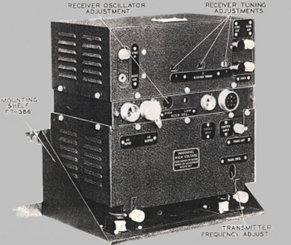
A typical ground based IFF Transponder, a BC-800, with the receiver at the
top and the transmitter below.
The MK III ground and mobile IFF units looked very similar from the outside. Most comprised two back to back aluminium chassis with the transmitter on the bottom and receiver on top. Separate top and bottom covers allowed the two units to be serviced and tuned up independently. However, the IFF transponder that was fitted to aircraft had a genemotor bolted to the underside along with the transmit circuits. The genemotor provided the voltages for the transmitter/receiver and drove a reduction gearbox which turned the code wheel and had a lever that protruded up into the receive section to rotate the variable tuning capacitor back and forth across the frequency range. The other chassis, with the receiver electronics, bolted on top of the power/transmitter chassis. As well as electrical sockets on the side of the chassis the unit had provision for a detonator, operated by an impact switch in the aircraft. Early versions were 12 volt but as aircraft moved to 24 v. systems the IFF genemotors also went to 24 volt.
The ground based Interrogator/Responsors such as the BC-800 pictured above included an 80v or 115v ac 400-1200 cycle mains supply to a transformer and two rectifiers. The 80v ac was standard supply to the radar set. The BC-800 Power Supply used a 5U4 medium HT rectifier and a 2X2 high voltage rectifier. Instead of a genemotor the unit had a cooling fan on the under chassis.
The BC-800 transmitter used a 2C26 valve, with 2500v on the plate, modulated by a 6SN7. It produced 8 microsecond pulses at a pulse repetition frequency (PRF) of 400 per second. Average power output was 2.4 watts but peak power could be 1000 watts. The transponders in the aircraft, ship or other vehicle used the same transmitter circuit but only around 500v HT on the 2C26.
The receiver in the Interrogator/Responsors had 956 acorn valves as the 1st and 2nd RF amplifiers, a 956 as the mixer, with a 955 acorn valve as the local oscillator. The IF consisted of 5 stages, all 6AC7's followed by a 6H6GT 2nd detector and then a 6AC7 1st video amplifier and a 6V6GT 2nd video amp. It was in fact very similar to the radar receiver on the radar set and the same as the receiver in the transponders, with the exception that in the transponders the variable tuning capacitor in the LO was mechanically rotated through 90 deg. to vary the swept frequency.
A synchronising pulse from the radar was fed to a synchronising and suppressor circuit comprising a 6AC7 amplifier/limiter and two 6SL7GT's as clipper and suppressor amplifier. This ensured the IFF pulse was transmitted in synchronism with the main radar pulse and off when waiting for a return echo. The transponders did not require this circuit.
References.
The
story of IFF (Identification Friend or Foe). IEE Proceedings, Vol.132, Pt.A,
No.6, October 1985.
Radar
Development to 1945. IEE, published 1988. Editor R. Burns.
TM
11-1133, Technical Manual, Radio Equipment RC-192-A, 1943.
Please note, this article is copyrighted.