
| VK2DYM'S MILITARY RADIO AND RADAR INFORMATION SITE. |
RECEIVE OUTFIT ACAS, RAN PATTERN
16303 - RECEIVER
PART OF
LOW POWER MF-HF RADIO COMMUNICATION
EQUIPMENT TYPE A618/ACAS
The RAN Type A618/ACAS was a general purpose ship-borne installation of transmitters and receiver. It consisted of major units:
| MF Transmitter | RAN Pattern 16301 | 330 Kc/s to 550 Kc/s continuously variable | 30 watts |
| HF Transmitter | RAN Pattern 16302 | 1.5 Mc/s to 17 Mc/s continuous or eight crystal controlled channels |
25 to 100 watts |
| Receive Outfit ACAS | RAN Pattern 16303 | 40 Kc/s to 30 Mc/s in nine bands | |
| Power Supply Unit | RAN Pattern 16304 |
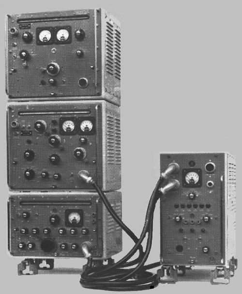
TOP TO BOTTOM - MF TRANSMITTER, HF TRANSMITTER, RECEIVER,
WITH POWER SUPPLY ON RIGHT.
As I’m concentrating on receivers at the moment the following covers only the Receive Outfit ACAS.
The receiver was made by TCA (Telecommunications Company of Australia, a Philips subsidiary) in 1961. As can be seen from the photo the cabinets allowed the other equipment to stack on top of the receiver, with the power supply separate.
It is a double conversion superhet which covers 40 Kc/s to 30 Mc/s in nine bands, the tuned circuits for which are in a rotatable turret mechanism. There were four degress of selectivity, the narrowest two being achieved by crystal filters. There were two RF stages, two IF stages and three audio stages, including a speech compressor. It had facilities for receiving CW, MCW and voice.
The weight of the receiver was 79 Pds. (35.9 Kg) and dimensions were 17 ¾” Wide x 15 ¼” Deep x 12 7/8” High (451mm W x 387mm D x 327mm H). That did not include the normally fitted shock mounts.
Sensitivity was good (which only means the manuals often give different ways of expressing the figures and it gets confusing trying to compare them). Signal to noise ratio was 10 dB up to 4 Mc/s and rose to 25 dB on the highest band.
An important aspect was the spec. for extraneous RF radiation which was less than 0.1 mv per metre at a distance of 1 nautical mile.
The selectivity was determined by the filters and crystals as follows:
| ATTENUATION | WIDE | INTERMEDIATE | NARROW | VERY NARROW |
| - 6dB | ± 4 Kc/s | ± 1.5 Kc/s | ± 0.4 Kc/s | - |
| - 30dB | ± 12 Kc/s | ± 6 Kc/s | ± 2.5 Kc/s | ± 0.8 Kc/s |
| - 60dB | ± 20 Kc/s | ± 12 Kc/s | ± 6 Kc/s | ± 6 Kc/s |
| - 90dB | ± 35 Kc/s | ± 25 Kc/s | ± 20 Kc/s | ± 20 Kc/s |
It had a compliment of 16 valves and employed a second mixer for double conversion on bands 3, 4 8 and 9. On the other bands this valve acted as an additional IF amplifier.
The frequency coverage is:
|
BAND |
FREQUENCY |
IF |
|
1 |
37 to 85 Kc/s |
455 Kc/s |
|
2 |
80 to 176 Kc/s |
455 Kc/s |
|
3 |
160 to 375 Kc/s |
1500 Kc/s and 455 Kc/s |
|
4 |
340 to 800 Kc/s |
1500 Kc/s and 455 Kc/s |
|
5 |
730 to 1710 Kc/s |
455 Kc/s |
|
6 |
1.54 to 3.62 Mc/s |
455 Kc/s |
|
7 |
3.3 to 7.8 Mc/s |
455 Kc/s |
|
8 |
7.0 to 16.6 Mc/s |
1500 Kc/s and 455 Kc/s |
|
9 |
14.8 to 33.2 Mc/s |
1500 Kc/s and 455 Kc/s |
In addition to the variable local oscillator, 4 crystal locked positions could be selected.
The audio output had separate headphone and speaker jacks and was capable of 2.5 volts into 100 ohms to the headphone jack and 33 volts to the speaker (line output) socket.
The receiver obtained its power from the Power Supply Unit and power consumption was approximately 65 watts. The voltages from the Power Supply were 6.3v ac for filaments, 250v dc for HT and -45v dc bias voltage.
The aerial input could accept aerials with a capacitance of 200 to 600 pF on the 6 lower bands and was designed for 75 W input on the higher bands. The set had an aerial trimmer for fine tuning. The aerial cable was normally routed to one or other of the transmitters which included a high speed antenna change over relay. The receiver was fitted with a muting relay to mute the audio when a transmitter was operating for break-in keying or "listening through".
The valve line up was:
V1
6AM5
CV4014
1st RF Amplifier
V2
6BA6
CV4009
2nd RF Amplifier
V3
ECH81
CV2128
1st Mixer and X1 Oscillator
V4
6AM5
CV4014
VF Oscillator
V5
ECH81
CV2128
IF Amplifier
V6
6BA6
CV4009
2nd Mixer and Oscillator, or IF Amplifier
V7
6AB6
CV2526
AGC Amplifier
V8
6BA6
CV4009
IF Amplifier
V9
6BA6
CV4009
Beat Frequency Oscillator
V10 6AL5
CV4007
Diode 1 – Signal Rectifier
Diode 2 – AGC Rectifier
V11 6AL5
CV4007
Diode 1 – Noise Limiter
Diode 2 – AGC Peak Limiter
V12 OA2
CV4020
Voltage Stabiliser
V13 6BA6
CV4009 1st AF Amplifier
V14 6AV6
CV2526 Audio Compressor
V15 6AM5
CV4014
2nd AF Amplifier
V16 6AQ5
CV4019
Audio Output
MR1 OA85
CV448
AGC Clamp Diode
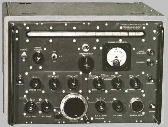
RECEIVER OUTFIT ACAS
The front panel controls, starting top left, are set out below. Most are self explanatory:
DIAL SCALE. This is a rotating drum similar to Collins receivers, with a pointer that moves along it. The scale is calibrated directly in frequency.
AERIAL. Accepts capacitive input on lower bands and 75 W on the higher frequencies.
AERIAL TUNING. A small trimmer capacitor.
H.T. ON – OFF When OFF the H.T. is transferred to a load resistor to prevent the H.T. voltage at the Power Supply from Rising too high.
BANDSWITCH. Nine positions and rotates a turret with the relevant coils, like the B40/B41 receivers.
SIGNAL STRENGTH METER calibrated in dB above 1 mv, but for convenience only and meant as an indicator and tuning aid, not an accurate level meter.
LOUDSPEAKER with PHONES underneath. Both can be used simultaneously. The Speaker impedance was 500 W and headphones 100 W.
LOWER. For servicing the set could be slid out on runners and then tilted upwards and locked in place to get access to the underneath. Pressing the two LOWER buttons (there’s one on each side of the front panel) allowed it to rotate back to horizontal.
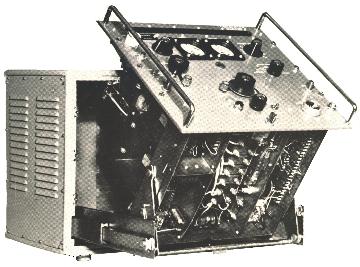
METHOD OF SERVICING CHASSIS
CROSS MOD. This varies the bias on the 1st RF amplifier to reduce gain
AGC OFF-ON
B.F.O. OFF-ON
BANDWIDTH WIDE – MEDIUM – XTAL NARROW – XTAL VERY NARROW
NOISE LIM. OFF – ON
COMPRESSION OFF – ON This acted to reduce audio level fluctuations when the AGC was switched off.
LOCAL OSC. 1 – 2 – 3 – 4 – VAR.
RF GAIN. This control adjusts the bias on the 2nd RF Amplifier and the 1st and 2nd IF Amplifiers.
LOCK A pushbutton dial lock.
TUNING
RELEASE Releases the chassis so that it can be pulled forward on runners and side rails. Before freeing the receiver from the case the operator had to unscrew 6 “difficult access” screws around the edges of the front panel.
B.F.O. TUNE - 1.2 Kc/s - + 1.2 Kc/s
AF GAIN
POWER INPUT A multi-pin connector with connections for H.T., Filaments, Bias voltages, Mute Relay, Speaker and Headphones.
EARTH
As well as providing all the power, the Power Supply Unit acted as the common interconnection point for the two transmitters and the receiver. It could be remote from the other equipment and could control their functions. Eg. In remote operation it switched the sets to CW, MCW or voice and had provision for a microphone and morse key.
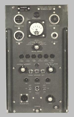
POWER SUPPLY UNIT
The receiver was very well built and robust as is needed on board ships with big guns. The provision of slides and tilt mechanism reflects the need to service it in situ.
I believe the RAN Corvettes that have been preserved in Australia, (eg. the Diamantina) have the A618/ACAS system on board.
References.
ROYAL AUSTRALIAN NAVY ABR 5043, Instruction Manual for LOW POWER MF-HF RADIO COMMUNICATION
EQUIPMENT TYPE A618/ACAS. 1961.
Please note, this article is copyrighted.