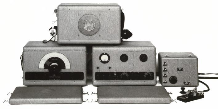
AWA 3B SET.
PSU WITH MIKE, HEADPHONES and SPEAKER ON TOP, RECEIVER ON BOTTOM LEFT, TRANSMITTER, AERIAL TUNER AND KEY ON RIGHT, COVERS IN FRONT.
| VK2DYM'S MILITARY RADIO AND RADAR INFORMATION SITE. |
THE 3BZ COAST WATCHERS WIRELESS SET.
This article was originally published in "Radiowaves", the magazine of the Historical Radio Society of Australia (HRSA). This version incorporates a couple of corrections and additional material that I had edited out of the HRSA version.
During World War II communications networks of Australian and American military and civilian personnel carried out surveillance of the Japanese forces in the New Guinea and Pacific areas, providing valuable strategic information and saving many downed airmen and shipwrecked sailors. They assisted in the rescue of the future President John F. Kennedy on PT109. Although they were mustered into various military organisations these brave men are generally known as the "Coast Watchers". They were often in great danger, operating behind enemy lines and isolated from help whilst having to contend with the savage climate, no supplies, disease and hostile natives. Sadly, a number were captured and summarily executed. For a better understanding of the privations and heroism of these wireless operators readers should seek the books listed in the references at the end of this article.
Many Coast Watchers relied for their communications on an Australian designed and manufactured transmitter/receiver outfit, the 3BZ. The 3BZ was the most famous of a series of communications equipment made by the large Australian company Amalgamated Wireless (Australasia), or AWA. That company had been formed in 1913 to combine the Australian interests of the Marconi and Telefunken companies and in 1922 the Australian Government took a controlling shareholding. AWA was given a mandate to provide wireless communications across Australia and in surrounding islands, New Guinea, the Solomons, Fiji, etc. where there were numerous widely separated plantations, airstrips, mines and settlements.
To meet these needs AWA developed a new "Teleradio" range of equipment starting naturally enough with the Teleradio 1, in 1935. This was a basic tunable transmitter with a tunable receiver side by side in a rectangular steel box, operated from batteries or a pedal generator based on a bicycle frame. (Suitable pedal power was readily available from the native labour force.) The tuning dials were typical of the 1930’s era of receivers with a round black bakelite housing which had a small knob at the bottom to operate the reduction drive and a window at the top to view the tuning scale. There was a demand for at least 200 Teleradios for fixed and portable installations and AWA set up base stations in major towns and islands to provide wireless links between stations and back to Australia. The operators and technicians were AWA employees.
By 1940 the Teleradio series had evolved into the model 3A. The receiver and transmitter/tuning unit of the 3A version were separate items, fitted into two rectangular steel boxes. The receiver (AWA Type *C3487) had a straight line dial covering from 105 meters (2.9 Mhz) to 13 meters (23 Mhz) in two bands plus an LF/MF segment in a third band. There were three models to cover different sections of the LF/MF band between 100-1500 Khz, identified by replacing the "*" with a 4, 5, or 6. The valve lineup of the receiver was a 1C4 RF amplifier, 1C6 oscillator/mixer, 1C4 IF, 1K6 detector/AVC/AF, 1D4 audio output and a 1K4 BFO. The general design for the 3A receiver was based on the newly introduced AWA dual band domestic receivers which featured straight line dials. The transmitter (Type J3908) was a simple unit fitted in another steel case, about the same size as the receiver case. The valves used were a 42 as the crystal oscillator, another 42 as the speech amplifier, driving a 6A6 as the class B modulator. The RF amplifier was an 807.
AWA 3B SET.
PSU WITH MIKE, HEADPHONES and SPEAKER ON TOP, RECEIVER ON BOTTOM LEFT,
TRANSMITTER, AERIAL TUNER AND KEY ON RIGHT, COVERS IN FRONT.
Then in April 1940 AWA made a radical design change and their new 3B equipment consisted of a five band (or four band plus one crystal channel) general coverage receiver (Type *C6770) covering 200 Khz to 30 Mhz, a two crystal channel CW and AM transmitter (Type 1J6798), a separate vibrator power supply in a metal case with a speaker included (Type D6799) and a small antenna coupling unit (Type J6847). The innovative pressed steel cases had rounded corners and strong clip-on metal covers with spring clips to protect the equipment and controls and to ease the rigours of manhandling it through thick jungles. The top covers were also held on by spring clips for quick and complete access to the internal components and the and bottom covers secured with 4 screws. The 3B receiver used indirectly heated valves comprising a 6U7G RF amplifier, a 6J8G mixer followed by a 6J8G IF amplifier, a 6G8 2nd IF and detector with a 6V6G audio amp. The main tuning control now incorporated a Muirhead type slow motion drive with a 180 degree scale and 54:1 vernier.
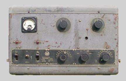
3B Transmitter
The 3B transmitter used the same valve line up as the previous Teleradio 3A, but the front panel layout was revised and the control and tuning knobs were conventional fluted type fitted with small engraved dial plates.
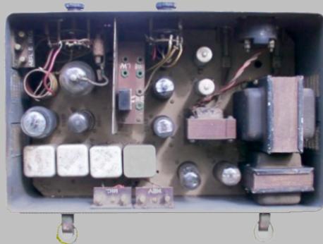
Interior of 3B Transmitter. This model has an in-built 240v Power Supply.
The 807 and output coil can be seen at the top left.
AWA described the new receiver for the 3B station in the “AWA Technical Review, Vol. 5 No.2, 1940” wherein the abstract reveals:
‘The receiver described below is a multi-range receiver with self-contained coils, covering a frequency range of from 30 Mc to 200 kc in five bands, the various ranges being selected by means of a switch. It is designed for operation from secondary batteries of 6 or 12 V, in which case a self-contained vibrator power supply unit is used for high tension, from an a-c source of 105/130 or 200/260 V and 40-60 cycles, or from a d-c source of similar voltage range. The total number of valves, excluding the rectifier, is five, and features include an efficient RF stage on all bands, a heterodyne beat oscillator for CW reception, A.V.C., and audio outputs of 600 ohms or 1.75 ohms. Crystal-controlled reception on a spot frequency may also be provided, in which case one variable tuning range is deleted, it’s place being taken by the crystal lock position.’
The Review goes on to say ‘The receiver has been designed for the more general applications in communications services where the higher cost and superior performance of the larger type of communications receiver are neither justified nor required.’

3B or 3BZ Receiver (well worn round knobs)
Even prior to World War II the Royal Australian Navy had organised many civilian wireless users in the Pacific islands into "spotters" nets, to alert the authorities to any suspicious activities. Some of these groups were issued with the new 3B sets. Following suggestions from the spotters as they honed their communications techniques, AWA developed the Teleradio 3BZ in 1942. Whilst it was similar to the 3B this version had a slightly modified receiver, a redesigned transmitter with six crystal channels and importantly the equipment was tropicalised to minimise the onset of mildew, rot and fungus.

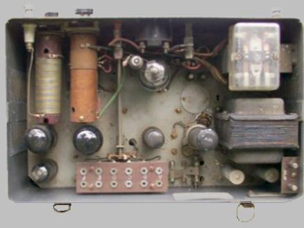
Interior view of 3BZ Receiver. There is space for an inbuilt power supply,
but this model was powered from a separate HT and LT Power Unit.
The receiver for the 3BZ had five tunable frequency bands or four plus one crystal, and there were a number of versions to operate on battery or mains power. The valve lineup was the same as in the 3B. The IF frequency was 535 Khz. The front panel controls were generally, from left to right, A.F. VOL., OFF--STD BY--PHONE--CW, TONE, a headphone socket, RANGE, R.F. VOL. although different models had variations of this layout. The receiver was not actually called 3BZ but was the "Superhetrodyne Receiver Type *C6770" where the "*" could be a 1, 2, 3 etc depending on the version:
C6770 standard 5 band, 6 or 12 volt vibrator model.
1C6770 5 band, 105-130v and 200-260v ac using an internal transformer and rectifier in lieu of the vibrator. The rectifier valve was a 5Y3G.
3C6770 4 band + 1 crystal, 6 or 12v.vibrator model.
In addition the receiver came in various mounting configurations with type numbers as follows:
1-C6770 Receiver C6770 in case R6836
10C6770 Receiver C6770 in case 14R6836 (19” x 8 ¾” rack mount)
2-1C6770 Receiver 1C6770 in case 1R6836
11C6770 Receiver 1C6770 in case 15R6836 (19” x 8 ¾” rack mount)
3-3C6770 Receiver 3C6770 in case 2R6836
The standard case had rubber feet that could be removed so the set could be bolted to a bench etc. Spacers were available to mount it into a 20” wide rack.
AWA literature mentions another model for DC mains supply of 105-130v and 200-260v dc. In this version the output valve was a 25L6G. It had a ventilated lid and bottom cover because of the heat generated by a large voltage dropping resistor. However, it does not seem to have gone into volume production.
The frequencies covered by the standard receiver were:
|
BAND |
RANGE (Mc) |
RANGE (METRES) |
|
A |
30 Mc to 9 Mc |
10 to 33 metres |
|
B |
11.1 Mc to 3.5 Mc |
27 to 85 metres |
|
C |
4.6 Mc to 1.5 Mc |
65 to 200 metres |
|
D |
1650 kc to 545 kc |
182 to 550 metres |
|
E |
515 kc to 200 kc |
580 to 1500 metres |
In the crystal version Band A or (occasionally) C was deleted and replaced with a fixed-tuned coil.
The valve filaments were arranged in two parallel strings which were connected in series for a 12 volt supply and in series/parallel for a 6 volt supply. This was accomplished by a special socket on the appropriate 6 or 12 volt battery power cable. In an emergency the receiver could be operated direct from a HT battery and the secondary batteries, bypassing the vibrator or the mains supply unit.
|
POWER CONSUMPTION |
|
6 Volt Battery |
12 Volt Battery |
AC Mains |
|
3.3 amps |
1.65 amps |
25 watts |
In later production the fixed neutralization capacitor C73 for the IF valve 6G8G was changed to a variable trimmer.

3BZ Transmitter
The 3BZ transmitter (Type J50062) was a new design with the antenna (aerial) tuner built in and 6 crystal channels and was identified as the "Teleradio 3BZ Transmitter" on the name plate. The valve complement included a 6V6 crystal oscillator, with a 6V6 microphone amplifier driving two 6V6's in push-pull to modulate an 807 RF amplifier. A heavy duty vibrator was included on the chassis and operation was from 12 volt dc only.
Interior of 3BZ Transmitter. Note vibrator at lower right next to transformer.
The 807 is centre top, just behind the meter. The socket for 6 crystals
is at the bottom.
Plate voltage to the 807 was 360 volts and the filaments were wired in series parallel to suit the 12 volt supply.
The frequency coverage of the 3BZ transmitter was 10 to 2.5 Mc (30 to 120 metres) with a power output of around 12 watts on CW and 15 watts on speech. Power consumption was 7.5 amps during operation and 1.5 amps on standby. Crystals in the range from 2.5 to 5 Mc could be fitted (when operating in the 5 to 10 Mc range part of the 807 power amplifier loading coil was shorted by the crystal switch, allowing it to be tuned to the second harmonic of the crystal frequency).
There was a low impedance antenna terminal to suit a ¼ wave Marconi antenna (used for less than 100 mile communications) and a separate 600 ohm high impedance terminal to allow a single wire feed half wave Hertz aerial, for 80 to 500 mile distances.
Headphones, key, microphone and either 6 or 12 volt accumulators and a small petrol charging generator completed the list. The microphone, cables etc were usually packed in the speaker case. Although the 3B speaker box, minus vibrator, was sometimes supplied, AWA also supplied the speaker Type D13503 but often any available speaker was used because the 3BZ now had it’s own in-built vibrator.
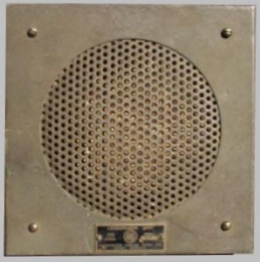
AWA Speaker Type D13503 for
3BZ.
As the 3BZ was powered by 12 volts dc, in situations where mains supply was available, a 240v ac to 12v dc Power Supply Unit was supplied. It contained a large step down transformer, choke and a large selenium rectifier.
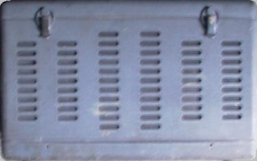
240 volt to 12 volt DC Power
Supply for 3BZ Transmitter.
Depending on circumstances, a typical Coast Watcher's set up could include items of equipment from the 3A, 3B and 3BZ range or in fact whatever was procurable, but they all tended to be known as the "3BZ". The all up weight was about 100 kg (200 pounds) including all ancillary equipment, with the generator accounting for 30 kg (60 pounds), whilst the receiver was a featherweight at only 16 kg (32 pounds). Compare that to the 50 kg (100 pound) AR88! The 3B and 3BZ steel cases were 41cm wide by 26cm high by 26cm deep (16"w x 10"h x 10"d). Later in the war other sets were used by the Coast watchers including the English Type A Mk3 and Type 3 Mk2 "spy" sets (see p.31 of OTB, Vol.36, No.3) and small Australian Army backpack sets such as the WS108 and WS208.
When the war reached the Pacific, the civilian population and AWA staff suddenly found themselves in the front line and pressed into service providing vital information on the enemy advances. They were joined by Australian Navy and Army groups and later the US forces provided spotters in the Pacific region. They moved through enemy lines carrying their 3BZ "lifelines", providing intelligence and calling up air and ship strikes to harass the enemy. The Japanese were very determined and ruthless in their efforts to eliminate their tormentors and any natives who helped them. Those AWA staff who survived wrote up vivid reports of their harrowing experiences, a few of which are included in the book "Seawatchers".
Incidentally, AWA did not sell the sets but rented them to the plantations etc. When war arrived the local economy collapsed and the users could see no point in paying the rental so AWA demanded the return of their radio equipment! The Navy had to make urgent representations to AWA to keep the radios where they were desperately needed and ended up paying AWA a substantial sum to buy them. Later AWA was awarded military contracts for additional quantities and more than 3500 of the 3B/3BZ sets were manufactured between 1941 and 1945.
The 3BZ was used by the Australian armed forces as a low power portable HF set and was supplied to US forces as the SC-CD-317-44 and the AMC145 and comprised the Receiver Type 15C6770, (Figs.4 and 5), Transmitter Type 1J50062, with a Loudspeaker Type D13503.
Today the 3BZ units are keenly sought because of their wartime significance and have even turned up in the USA and Europe. Eagle eyed collectors are quick to notice the differences between the 3A, 3B and 3BZ, as well as the various Type Numbers. The 3A and 3B models are particularly scarce.
AWA continued the 3BZ receiver series through to the *C6940 for various marine and HF bands and special requirements and after the war produced an improved version known as the Type 1C7567, with miniature valves, as a general communications receiver. This had fancy knobs and a chrome escutcheon with the control functions engraved, to appeal to the post war commercial market. AWA developed the “Teleradio” range over the years, finally manufacturing a fully transistorised version as the "Teleradio 8" transceiver in the 1970's.
References.
The Coast Watchers. E. Feldt. Melbourne 1946. Oxford University
Press. Hard Cover. Commander Eric Feldt set up the Navy Coast Watching Service.
The Coast Watchers.
E. Feldt. Melbourne 1991.
Penguin Books. ISBN 0 14 014926 0. Paperback edition.
The Seawatchers,
the Story of Australia's Coast Radio Service. L. Durrant. Angus and Robertson Publishers,
Sydney. 1986. ISBN 0 207 15198 9.
The Private War
of the Spotters. A history
of the New Guinea Air Warning Wireless Company. A.E. Perrin. Published by
the NGAWWC Committee. 1990. ISBN 0 7316 7292 5. Alex Perrin was a 'Spotter',
as all members of 'NGAWW' came to be known.
AWA Technical Review Vol.5 No.2 1940. Gives a description of a new communications
receiver that became the 3BZ receiver.
"Radiowaves" the magazine of
the HRSA (Historical Radio Society of Australia)
Please note, this article is copyrighted.