CONSTRUCTING A 1930's MOPA TRANSMITTER
Up until the late 20's, most amateur transmitters consisted of simple one-tube self-excited oscillators. Be they Hartleys, TNT's or Tuned-Plate-Tuned-Grid styles, most of them suffered the ill's of '29. Not the least of these was frequency instability caused by antennas blowing in the wind. One needs only to listen to the AWA's annual Bruce Kelley 1929 QSO Party to hear what the bands probably sounded like during the time when these simple rigs ruled the airwaves.
During the 1929 re-vamping of radio regulations and the call for increased control over frequency stability, a new type of transmitter began to evolve ... the Master-Oscillator-Power-Amplifier or MOPA. Having an extra stage of isolation between the (usually) self-excited oscillator stage and the antenna, meant that changes in antenna capacitance as antennas swayed in the breeze, would no longer directly affect the oscillator.
Early QST articles described one-tube amplifiers that could be lashed to the oscillator in order to realize the benefits of isolation. Later articles described complete transmitters, usually using two tubes, to keep duplication simple and to encourage builders to make the change ... and to 'go modern' in the new era of post -'29 amateur radio.It was precisely the same sort of thing that eventually motivated me to begin construction of a MOPA-styled transmitter. It seemed that every '29 QSO Party was an invitation for mother nature to unleash gale-force winds upon my location and praying for calm weather each December just wasn't working. After many years of enduring the pain, I finally decided that it was time to end the suffering and not have to worry about the weather.
I researched numerous QST articles, pushing for the change to MOPAs, starting in 1929 and gradually gaining momentum in the early 30's. The transmitter that I chose to build was one based on a QST article by George Grammer, W1DF (QST Assistant Technical Editor), "More Power With Better Frequency Stability - Practical Suggestions For Oscillator-Amplifier Transmitter Design", appearing in the February, 1931 edition. The article described the mating of various types of oscillators to single tube amplifiers and the advantages to be gained by doing so. Various 'practical circuits' were discussed as were the nuances of efficiently driving the final amplifier and correctly neutralizing it . For anyone contemplating a MOPA, this article is a must-read. I would classify it as a QST 'classic'.
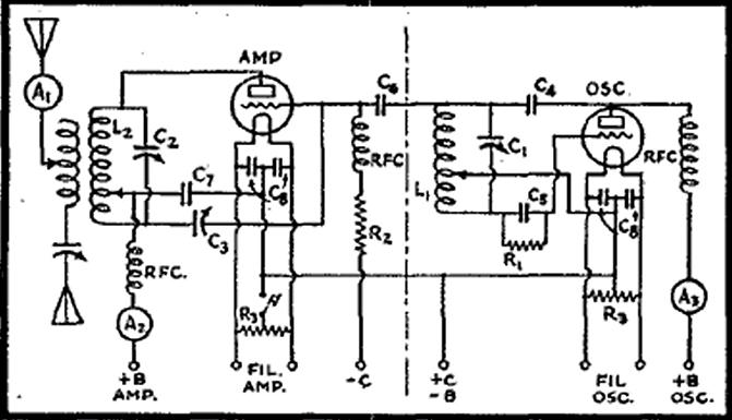
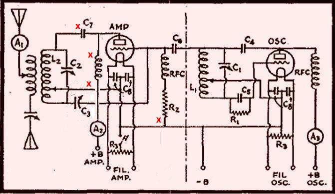
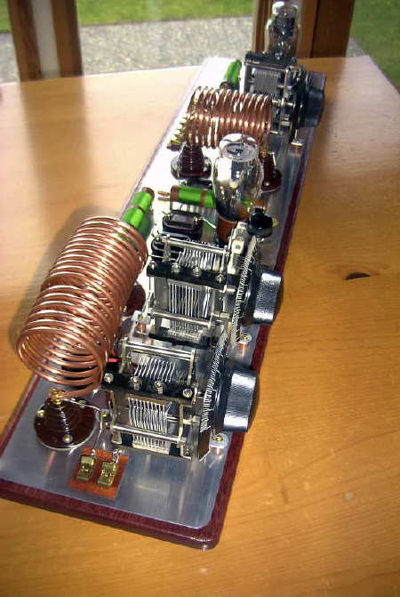
The circuit that I chose to emulate is shown below, consisting of a type '10 triode Hartley oscillator driving a second type '10 in Class C:
I chose, however, to make several convenient modifications to the circuit as described below.
Not desiring to electrocute myself changing coils during a late night QSO Party band change, I decided to remove the high voltage from the amplifier plate tank coil by converting from series-feed to shunt-feed. This was done by moving C7 to the plate side of the coil and then shunting the plate voltage via the original plate line RFC. To keep things simple, there would be no external bias (C) supply. Operating bias would be generated by directly grounding the amplifier's grid leak. Since I decided to connect both filaments (cathodes) in parallel and feed from just one filament supply, one of the center-tapped filament resistors could be removed. Keying was done by bringing the cathodes to ground via center-tapped filament resistor keying. Along with the amplifier's grid leak, both tank coil taps were also directly grounded.
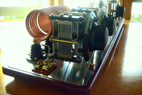
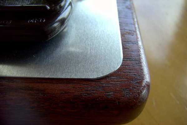
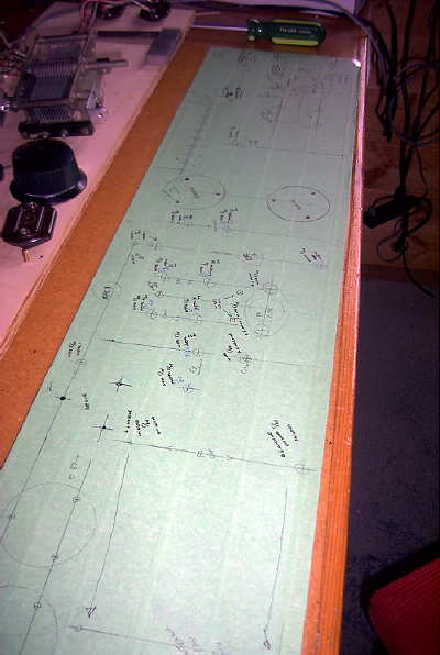
Having a schematic plan in hand, the next task was to play with a suitable physical layout. My operating space for any '29 equipment is very limited and this space, more than anything, would dictate the shape and size of the project. A conventional somewhat square layout would be too deep for my space so I needed something narrower and longer. Having enjoyed the pleasing layout of my Longfeller, I began to explore this style of layout next. I eventually was able to plan a suitable parts layout plan but was not overly-motivated to begin construction ... further thought gave me the inspiration needed to begin construction. I've always enjoyed the physical appearance of many of the 1930's transmitters, as construction style moved quickly from breadboard to metal chassis. There was a short period where both styles were combined ... a metal ground plane mounted on a wooden breadboard. This was the method that I chose, even knowing that the work involved in this type of construction is rather nightmarish. I can see why this style was short-lived. Nevertheless, I love the somewhat 'art-deco' appearance of parts reflecting in the metal combined with the rounded corners and the hardwood borders.
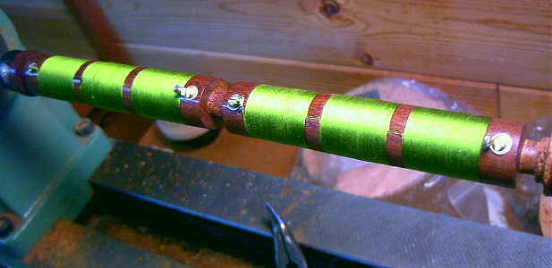
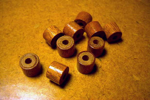
After manufacturing the required RF chokes (turned and wound on the lathe) as well as making the spacers needed to insulate many of the components from making contact with the aluminum plate, construction began by making a full-size mockup on plywood, using all of the parts that would be used in the finished rig.
The mockup was photographed so that various wiring paths could be planned. This turned out to be a very worthwhile step as a number of small layout quirks (such as having the open plates of the capacitors scraping against the tank coil) were avoided in the finished model.
Once the parts placement was finalized, work began on fabricating the aluminum groundplane. Each component was carefully measured and the required drilling locations were layed out on the plate that had now been covered with painter's masking tape. The 20-gauge aluminum plate was purchased from the scrap bin of my local Metal Supermarket and came with a plastic protective covering as well.
All of the holes (84 in total) were carefully layed out and drilled. Many of the holes had to be larger than the screws going through them so as not to make contact with the groundplane.
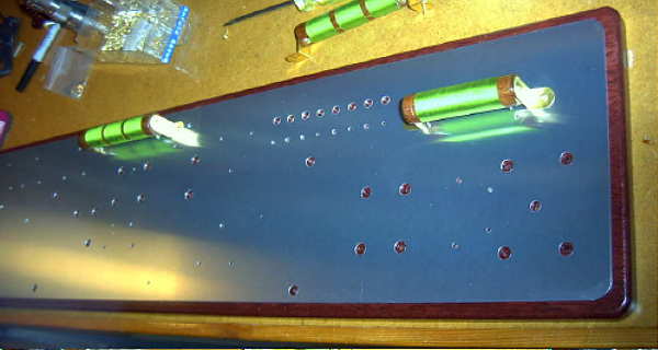
Once the plate was completely drilled, the mounting of components began. Many were fastened 'through hole' with machine screws and soldering lugs beneath so that some of the wiring could be concealed from view. Many of the holes were tapped and threaded so that components or spacers could be screwed directly to the board with brass machine screws. Once all of the components had been mounted, wiring could begin.
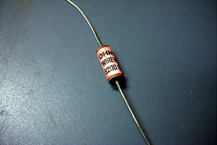
All 'period' resistors were manufactured from modern ones by first sanding their bodies clean and then gluing a painted 'OHMITE' tag onto the body.
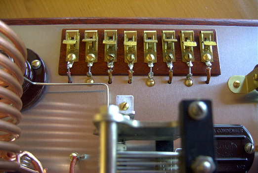
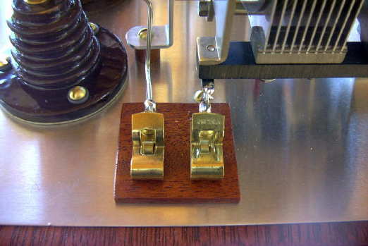
All power and keying terminals were mounted on an insulating hardwood strip as were the antenna / ground connections.
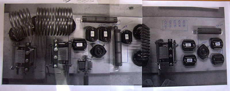
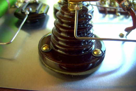
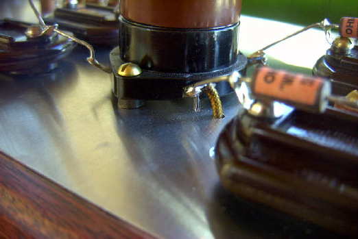
All beehives were mounted using homebrew washers cut from soft lead-sheet. These lessen the chance of cracking one of these hard-to-find beauties.
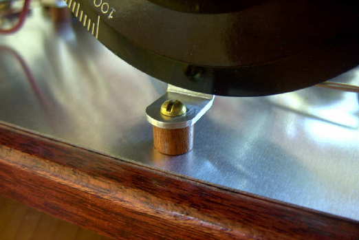
Variable capacitors requiring insulating from ground (oscillator, PA and neutralizing) were raised on spacers and fastened via a tapped hole in the breadboard.
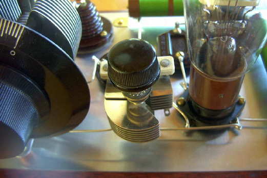
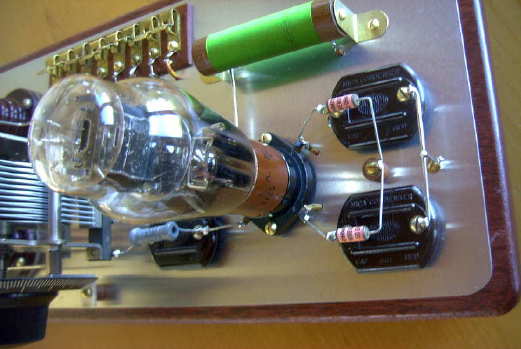
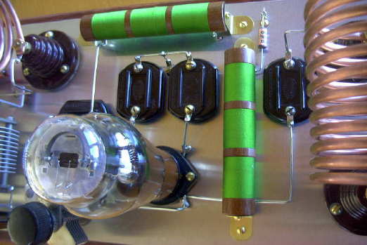
The tube sockets were also raised above ground to allow above chassis connections to be made. The neutralizing capacitor was also raised and insulated from ground. The oscillator (Hartley) stage along with the 50 ohm filament resistors. The keying line, common to both tubes, is taken from the center post, which feeds through to the underside of the breadboard.
The amplifier stage, along with oscillator coupling capacitor, filament bypass caps and grid / plate RF chokes.
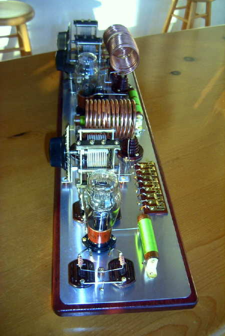
The finshed MOPA measures 7 1/2" x 31". The transmitter produces about 15 watts output on both 80m and 40m at an efficiency of just over 50%. Amplifier grid drive is approximately 9ma. Final plate current is around 65ma. Keying is very stable with just a slight trace of chirp, with both stages being keyed...and ... I can now look forward to the next '29 QSO Party without worrying about the windy weather!