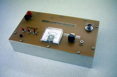
A friend of mine asked me if I was interested in building him a beacon transmitter for the licence-free LOWFER band (160 - 190kHz). Knowing how important it was to him and seeing an opportunity to refine my 'Manhattan-style' building skills, I agreed to put something together for him. One of the work-horse designs that has proven itself as a reliable and versatile transmitter is the one designed by Lyle Koehler (KØLR). It seemed that this transmitter would satisfy his requirements and would make a suitable transmitter for his new beacon.
Since the transmitter was to be used as a 24/7 beacon, I decided to add the K1EL K-ID2 beacon identifier chip, a $6 IC that comes with seven of your own pre-programmed messages. The chip offers both normal speed CW as well as two QRSS speeds which frees-up the station computer from having to control the beacon.
The only other change to Lyle's design was to add both 12V and 5V regulation to the board as well as separating the DC line to the final amplifier from the rest of the circuitry.
Here is a drawing of the circuit with the changes incorporated. The three toggle switches are used for changing the beacon's message while the three-position switch is used for selecting "KEY-DOWN", "CW" or "BEACON" mode.
After breadboarding the transmitter to check things out, the circuit was built using the Manhattan construction style. The thing I really like about this method is its flexibility for making quick part changes as well as allowing you to use those parts cut from old VCRs and computers, that have really short leads!
The Manhattan pads were all punched by hand but the pads used for the IC chips were obtained from FAR CIRCUITS. I used to etch these myself until I discovered these 'perfect' ones and at 20 cents each, they are well worth the money!
The crystal used was an old surplus 3MHz one used in the divide-by-sixteen mode of the 4060 oscillator. The 4060 produces about 3 volts of square-wave output at 188.540 kHz, which is then fed into the complimentary-pair final amplifier.
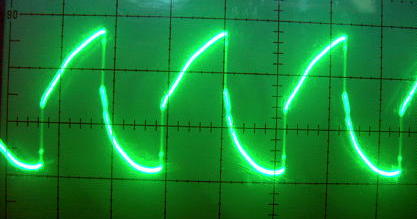
The final amplifier of the beacon produces the legal '1-watt DC input' power stipulated under Part 15 LOWFER rules. At 12.6V DC, final current is 77ma (1080mw actually), with a measured output of 700mw into a 50 ohm load. When run at 20V DC, the final drew 115ma for 2.3W input and a measured output of just over 1600mw. At 1W input, the final transistors run stone-cold but at the higher power level, a heat-sink would be required on the transistors.
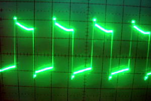
The output from the final, before filtering, is still somewhat square and harmonic-rich:
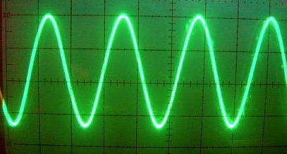
As shown below, the onboard Low Pass Filter will clean-up the output waveform as well as reduce harmonic content. Note that the value of capacitor (.018uF) should be experimented with (a few .001 up or down) in order to achieve optimum output. I ended up with an additional .002 uF in the filter for a total of .02uF.
For more information on LOWFER BEACONS and LF activity, please see the links section below.
LF LINKS
136kHz AT G3YMC - A good source of 'hands-on' information.
ON7YD - AMATEUR RADIO ON LONGWAVE - Probably one of the best sources of practical construction info. It's all here!
QRSS AND YOU - Clint Turner's excellent QRSS page. A must see!
LONG WAVE CLUB of AMERICA - Get the latest LF news here. Interactive Longwave Message Board, archived articles, software links, wav. files, propagation articles. LOWFER and MEDFER targets. An excellent site.
DIGITAL SITE of ALBERTO (I2PHD) and VITTORIO (IK2CZZ) - Download the latest versions of ARGO, SPECTRAN and others.
AMRAD L.F. PAGE - Equipment details.
W4DEX ON THE WWW - LOWFER 'NC'. Station description. LF/MF information.