If you are anything like most radio 'nuts', you probably had a crystal set when you were a kid. Thinking back to those good old days, I recall that I could only hear two local stations on my crystal radio. I had always believed that you just couldn't hear very far on a crystal set.....until I ran across this picture!
It was a picture of Al Klase's wonderful "Crystal Radio DX Contest" station! I was amazed to learn that it was even possible to hear 'DX' on a crystal radio and, apparently, there was a large group of very active crystal radio DXers. I was hooked on learning more about this fascinating possibility!
PUSHING THE BOUNDARIES... With some further investigation I turned up the 2001 contest winner, Mike Tuggle in Hawaii. Mike had logged 63 stations and Cuba, all on the AM broadcast band! It turned out that Mike, after years of experimenting, had developed an extremely efficient DX set, which he called the "LYONODYNE 17".
Mike's elegant set is not only a work of art but also 'state of the art', using large diameter basketwound Litz-wire coils and high quality, low loss ceramic tuning capacitors. To be 'legal' in the crystal set community, the radio must be completely "passive", meaning no amplification of any form is allowed. The only power used must come from the antenna, making these DX Contest results even more amazing!
LOCATION! LOCATION!... Crystal-set DXers are up against two problems: SELECTIVITY versus SENSITIVITY. If you live in a city or near a large city that has several 'blowtorch' AM signals, your main focus will be on separating signals so that the weaker DX can be heard between the blowtorches. On the other hand, if you live in the country, you don't have to worry so much about separating strong locals; you can run things 'wide-open' enabling you to log some of the weaker DX signals. Living away from the city certainly makes life simpler for crystal radio DXing but don't despair if you are a city-dweller. One of the DX Contest winners lived in San Jose and still managed to log plenty of DX!
QUICKY BASICS...The diagram shows a simple basic crystal radio.
In the city, with a good antenna, such a set will hear plenty of locals but it is unlikely to hear any DX. Take it out to the campground for the weekend however and even a simple set like this is capable of logging DX. Since most of us live in or near the city, we need to look at ways of transforming the basic set into a DX machine!
In order to separate the strong locals, the tuned circuit (L-C) must have as high a 'Q' as possible. Placing the diode and headphone load at the top of the circuit will result in strong signals but poor selectivity. The impedance of the headphones will load down the tuned circuit, lowering its 'Q'. The result is very poor selectivity.
Tapping the diode/headphone load at a lower point in the tuned circuit results in less 'Q-lowering' of the circuit. The result is a higher degree of selectivity. You don't, however, get a free ride! The higher selectivity diode tap point results in less overall voltage being fed to the headphones. Signals are weaker but easier to separate! The challenge of building an efficient tuner is to find the right balance between selectivity and sensitivity!
There are a few more improvements that will help the 'basic set'. More sensitivity as well as more selectivity can be realized in the antenna circuit. A separate antenna coupling coil that will couple the antenna into the main tuning coil will result in a further overall improvement.
Further improvements in both sensitivity and selectivity can be achieved by actually tuning the antenna system to resonance. Your type of antenna system as well as the part of the AM band that you are tuning will determine which system works best. The series-tuned antenna coupler is best suited for tuning large antennas, especially those with large horizontal runs ("top hats"). The parallel-tuned antenna coupler is better suited for tuning shorter antennas, such as vertical wires, masts or whips - those without top hats.
A series of test clips or a simple switching system can be used experimentally to determine what works best for you. Making this effort is important as it goes a long way towards avoiding initial disappointment with the crystal set's performance. Such a system as this is called a 'double-tuned' set. With care and attention to construction, such systems are capable of hearing DX signals.
Adding a tuning capacitor in series with the antenna permits a long antenna to be tuned very effectively by a parallel-tuned antenna coupler. In fact, this is the method-of-choice for many crystal set listeners. To avoid the complication of an extra tuning knob, a single-knob, two-gang variable capacitor can be used as shown here. The added variable capacitor can be placed instead in the ground leg. This 'enhanced parallel-tuned' coupler can be very effective in peaking up desired signals while knocking down nearby interference. I have found the use of a tapped coil in this circuit to be very beneficial in achieving optimal Q for the portion of band being tuned. One might even decide on using separate 'high-band' and 'low-band' coils for this circuit.
Although you may now be able to hear some DX, chances are you are still bothered by at least one (if not several) local 'pest' signals. Further gains in selectivity can be had by the addition of another tuned circuit, called a 'wavetrap'. By coupling this circuit to the detector coil, this circuit can be tuned to the same frequency of the pest signal, absorbing much of its signal-killing strength at the detector, while not adversely affecting the strength of wanted signals. More than one wavetrap may be employed to tackle more than one pest signal. With a high Q wavetrap, very loose coupling is usually best.
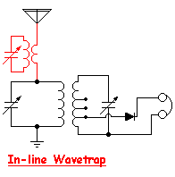
Another method that some find successful is the use of an 'in-line' wavetrap in the antenna circuit. The smaller secondary winding can be wound either on top of the primary or on one end. One or two in-line wavetraps can often be used to effectively knockdown the strong pest signals.
Another important improvement can be made in the headphone circuit. If you are using the old standard style of headphones (Brush, Baldwin etc) they must be high impedance phones. The modern low-impedance 'walkman' style phones will load-down the detector circuit too much, seriously degrading selectivity and signal strength. Even high impedance phones will cause unwanted loading of the detector circuit. Using a low-loss audio transformer with a very high impedance primary between the phones and the detector will reduce the problem and often great gains in selectivity can be achieved. Look for a high quality audio transformer with a primary impedance of at least 100K ohms and a secondary to match your phones. Try to avoid the small printed circuit transformers used in transistor radios - this is a case of the bigger, the better.
One of the greatest improvements made on my own DX set was changing from a pair of vintage high-quality Baldwin phones to a pair of headphones made from an old Navy 'sound-powered' handset. Most crystal radio DXers are utilizing this style of headphone. They are extremely sensitive! Old handsets are always available on e-Bay and can often be had at a bargain price. Often the earpiece transducer as well as the microphone element are identical and a single handset will yield a nice set of phones. The elements can be removed and placed inside an old set of headphone covers or hearing protectors. I think that going 'sound-powered' was the best single improvement that I was able to make when my DX set was evolving.
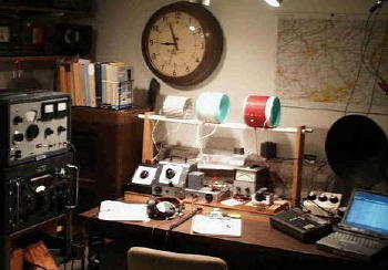
BUILDING YOUR DX SET... Start by thoroughly checking out the many links shown at the bottom of the page. There is a huge amount of good information available on the web. Back when I was doing this, there was a very active 'Yahoo Crystal Radio Group' group to provide an interactive forum for asking questions. That group is still there but seems fairly dormant now. There is now a very active group to be found on Facebook in the 'Crystal Set Radio Group' (see link at the bottom of the page). Another great interactive site may be found on The Radio Board's forum page. There are a lot of folks from the original Yahoo Group with much knowledge to share (see link below).I would suggest that you consider an experimental loose-coupled test bench. This will allow you to easily make coil changes and adjust coupling between circuits. A fine example of a loose-coupled set is shown below. It was built by Larry Pizzella in San Jose and was used by him to win the 1999 DX Contest!
Although the loose-coupled coil rack is not visible in the photo, my own DX set was built along these same principles.
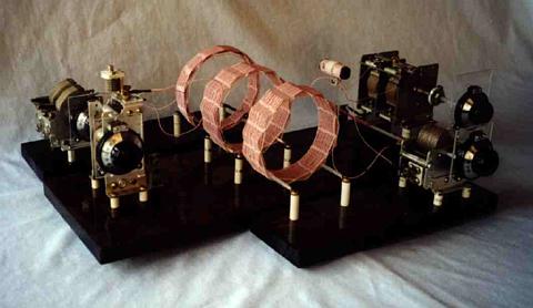
Many different coil styles, wire diameters and antenna tuning circuits were tried over the space of several months. This is the schematic diagram of the final arrangement used in my 2002 DX Contest set.
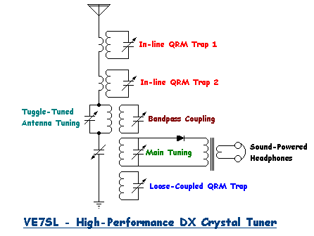
This is a 'triple-tuned' arrangement. There are vernier reduction drives on all tuning capacitors as tuning is very sharp on all circuits. Because of the great abundance of 'blowtorch' signals within 15 miles of my location (seven 50 KW locals) heavy trapping of pests is required. Both sensitivity and selectivity are good; on evenings of good propagation, signals from Alberta and California can become 'pests' in themselves! Both in-line traps and loose-coupled traps have proven to be very effective.
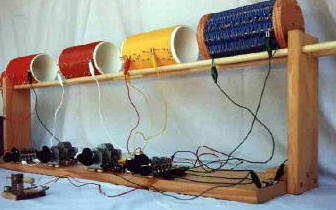
Not visible in the photo are the in-line wavetraps shown here.
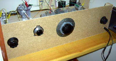
Calibrated dials help to quickly zero in on pest frequencies. During the DX Contest 80 different stations were logged on the AM band, the furthest DX catch being WOAI in San Antonio, Texas. U.S. stations in WA, OR, ID, CA, UT, NV, MT and CO as well as Canadians in BC, AB, and SK were heard. Nine 1 KW stations along the west coast were logged as was the little 500 watter CKBX in 100 Mile House, B.C. As well as the DX set performed however, there was still much room for improvement!
CRYSTAL RADIO LOGBOOK
FREQ
STATION
LOCATION
POWER
550 CBK WATROUS, SK 50KW 550 KARI BLAINE, WA 2.5KW 560 KPQ WENATCHEE, WA 5KW 570 KVI SEATTLE, WA 5KW 580 KFXD NAMPA, ID 5KW 580 KTMT ASHLAND, OR 1KW 600 CKBD VANCOUVER, BC 10KW 650 CISL VANCOUVER, BC 10KW 670 KBOI BOISE, ID 50KW 690 CBU VANCOUVER, BC 50KW 730 CJNW VANCOUVER, BC 50KW 750 KXL PORTLAND, OR 20KW 770 CHQR CALGARY, AB 50KW 780 KKOH RENO, NV 50KW 790 KGMI BELLINGHAM, WA 1KW 800 CKOR PENTICTON, BC 500W 800 CHAB MOOSEJAW, SK 10KW 810 KGO SAN FRANCISCO, CA 50KW 820 KGNW SEATTLE, WA 5KW 830 CKKY WAINRIGHT, AB 3.5KW 840 KSWB SEASIDE, OR 500W 840 CKBX 100 MILE HOUSE, BC 500W 850 KOA DENVER, CO 50KW 860 KPAM TROUTDALE, OR 10KW 870 KFLD PASCO, WA 250W 880 KIXI MERCER ISLAND, WA 10KW 880 COOL EDMONTON, AB 50KW 890 CJDC DAWSON CREEK, BC 10KW 900 CKMO VICTORIA, BC 10KW 910 CKDQ DRUMHELLER, AB 50KW 920 KXLY SPOKANE, WA 5KW 930 KBAI BELLINGHAM, WA 500W 940 CJGX YORKTON, SK 50KW 950 KJR SEATTLE, WA 50KW 960 CFAC CALGARY, AB 50KW 980 CKNW NEW WESTMINSTER, BC 50KW 1010 CBR CALGARY, AB 50KW 1040 CKST VANCOUVER, BC 50KW 1060 CKMX CALGARY, AB 50KW 1070 CFAX VICTORIA, BC 10KW 1090 KYCW SEATTLE, WA 50KW 1130 CKWX VANCOUVER, BC 50KW 1160 KSL SALT LAKE CITY, UT 50KW 1170 KPUG BELLINGHAM, WA 5KW 1180 KOFI KALISPELL, MT 10KW 1190 KEX PORTLAND, OR 50KW 1200 WOAI SAN ANTONIO, TX 50KW 1210 KBSG AUBURN, WA, 10KW 1210 KZTS SUNNYSIDE, WA 1KW 1240 KGY OLYMPIA, WA 1KW 1240 KOFE ST. MARIES, ID 500W 1250 KKDZ SEATTLE, WA 5KW 1250 KWSU PULLMAN, WA 5KW 1260 CFRN EDMONTON, AB 50KW 1260 KLYC McMINVILLE, OR 850W 1270 CHAT MEDICINE HAT, AB 10KW 1270 KTFI TWIN FALLS, ID 1KW 1280 KIT YAKIMA, WA 1KW 1290 KGVO MISSOULA, MT 5KW 1290 KUMA PENDLETON, OR 5KW 1290 KKSL LAKE OSWEGO, OR 5KW 1300 KOL SEATTLE, WA 5KW 1300 CJME REGINA, SK 10KW 1310 CHLW ST. PAUL, AB 10KW 1320 CHMB VANCOUVER, BC 50KW 1340 KLKI ANACORTES, WA 1KW 1360 KKMO TACOMA, WA 5KW 1370 KAST ASTORIA, OR 1KW 1410 CFUN VANCOUVER, BC 50KW 1470 CJVB VANCOUVER, BC 50KW 1510 KGA SPOKANE, WA 50KW 1520 KKSN OREGON CITY, OR 15KW 1530 KFBK SACRAMENTO, CA 50KW 1550 KCCF FERNDALE, WA 10KW 1590 KLIV SAN JOSE, CA 5KW 1600 KVRI BLAINE, WA 10KW 1620 KYIZ RENTON, WA 1KW 1640 KPBC LAKE OSWEGO, OR 1KW 1660 KXOL BRIGHAM CITY, UT 1KW
BUILDING HINTS 1. Avoid winding coils on wood or cardboard forms. These materials, even when sealed, will absorb 'Q -killing' moisture and impair both selectivity and sensitivity. Use either styrene sewer pipe couplers, thin-walled black ABS plumbing pipe or white PVC tubing. For really high-Q coils, experiment with 'basket-weave' or 'rook' style windings.
2. Avoid small guage wire for coils. Large diameter coils made of solid wire (#12-#18) are easy to wind. Try to space the coil winding so that each turn is at least one wire-diameter away from its neighbor. Stay away from taps if possible. Taps can quickly rob 'Q' from a coil.
3. Make your coils big! No smaller than four inches in diameter is a good starting point.
4. Use the best quality tuning capacitors that you can find. The ones with ceramic insulation are best. Try to avoid mounting them directly against moisture absorbing surfaces, such as wood. Insulate them with ceramic or plexi spacers. Use insulated shaft extensions to avoid hand-capacitance effects.
5. Devise a method of comparing different diodes. A switching arrangement that will accomodate more than one diode will allow some real-time 'A-B' diode comparisons. Test your diodes on a DX signal as a diode that produces the best signal on a strong local may not be the best one for hearing weak DX. Most older 1N34 diodes appear to be hotter than those manufactured today. Consider the use of Schottky diodes that have proven to be extremely sensitive when used in high-Q systems.
6. Don't wait too long before considering sound-powered phones. They are a must if you want to hear the weak ones. Watch e-Bay for some good bargains.
7. Use vernier dials/drives on all controls as the high-Q circuits often tune very sharply. Detector tuning and antenna tuners should have a logging scale so that tuning is repeatable.
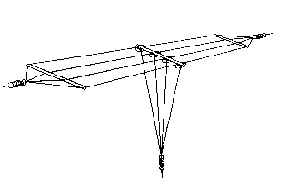
8. Get your antenna as high as possible. If it can't be very long, then give it lots of top-loading as shown below.
9. Pay attention to your ground system. Buried wires acting as a ground counterpoise work well. Tie into the copper waterpipe system if possible.
10. Keep notes on your experiments.
11. Don't give up! Eventually you will break through and hear DX. On nights of good propagation the band will come alive with signals.
CRYSTAL RADIO LINKS
THE LYONODYNE - A detailed description of Mike Tugggle's DX Contest winning set. Probably one of the most efficient DX sets ever built!
A CRYSTAL DX SYSTEM -A superb description with all building details...a must see!
STAY TUNED - Everything you need to know about sound-powered phones is here. Hundreds of crystal radio building plans, schematics and suppliers. A superb site!
FACEBOOK Crystal Set Radio Group - A very active group of over 5,000 members with all ranges of experience!
FACEBOOK Crystal Radio DX Contest Group - A new group to discuss the next DX Contest!
CRYSTAL RADIO SET SYSTEMS - Design, measurement and improvements. Detailed circuit analysis by a brilliant engineer, Ben Tongue.
SCOTT's CRYSTAL RADIOS - Huge selection of headphones, including Sound-Powered phones for sale!".
KEN HARTHUN's SW SET - Build a Short-Wave version of the 'Mystery Set'
KEN HARTHUN's SW SET EXPERIMENTS - 'Mystery Set' improvements.
CRYSTAL-RADIO - Dick Kleijer's first class site. Excellent info on re-building capacitors for higher - Q as well as detailed measurements of L-C "Q - killers".