
23-04-2000 TS-50S "Hello" displayed during TX
Author: Kenwood Communication, inc.
 +-------------------------------------------------+
 ¦      TS-50 <--> AT-50      Communication        ¦
 +-------------------------------------------------¦
 ¦        as measured/discovered by DF6KR          ¦
 ¦        No guarantee for whatsoever....          ¦
 +-------------------------------------------------+


Communication method:   Serial interface
Tranfer rate:           4800 bps
Synchronization:        Start-stop (Asynchronous)
Parity:                 None
Signal format:          TTL level (!)

                +---+
        +-------------------+
        ¦       +---+       ¦   1:  Ground
        ¦   1   ¦ 2 ¦   3   ¦   2:  TT (TS50<--AT50)TTL!

 ACC    ¦ +---+ +---+ +---+ ¦   3:  TS (TS50-->AT50)TTL!
        ¦ ¦ 4 ¦   5   ¦ 6 ¦ ¦   4:  N.C.
        ¦ +---+       +---+ ¦   5:  ATG (signal ground)
        +-------------------+   6:  +13.8V from TS50
      Rear Panel Connector ACC

Timing:

1. at Power-on:
===============

    +------------------+ ++1         ++3++6
TT--+                  +---------------------->
    |                  |  |           | |
    |       1.45 sec---+  |           | |
    +--+                  ++2         +-+4,5
TS--+  +--------------------------------------->
       |                   |<- 600ms->|
    0  + 90ms               resume time       t

Signal:
       1         3              6
TT: ;;;;;0C;___0D01;__________0F11;
             2        4    5
TS: ________0C;_____0D01;0F11;____

1: Power on comm.
2: Power on answer
3: Auto on request
4: Auto resume finished
5: ok at50
6: ok answer ts50


2. DOWN-UP-Communication
========================

TT: 0E02;__________0F11;__   - UP from 1.8 to 3.5
TS: _____0E02;0F11;_______

same:
0E04;0E04;0F11;0F11;   UP 3.5 --> 7
0E05;0E05;0F11;0F11;   UP 7   --> 10
0E06;0E06;0F11;0F11;   UP 10  --> 14
0E07;0E07;0F11;0F11;   UP 14  --> 18
0E08;0E08;0F11;0F11;   UP 18  --> 21
0E09;0E09;0F11;0F11;   UP 21  --> 24.5
0E0B;0E0B;0F11;0F11;   UP 24.5--> 28
0E0C;0E0C;0F11;0F11;   UP 28  --> 29
0E01;0E01;0F11;0F11;   UP 29  --> 1.8

DOWNs
0E0C;0E0C;0F11;0F11;
0E0B;0E0B;0F11;0F11;
.
.
0E01;0E01;0F11;0F11;


TUNE:             0D03;0D03;0F41;0F41;
AUTO OFF (THRU):  0D00;0D00;
AUTO ON:          0D01;0D01;
tune error:       0d03;0d03;0F83;0F83;
  IF-10D                                                    PC-DB9
_________                                                _____________
DIN6P.
  1. o GND------------------------------------------------o 5.(GND)
  2. o TXD------------------------------------------------o 2.(RXD)
  3. o RXD---------------------------I>I------------------o 3.(TXD)
                                  |--I I--|
  4. o CTS-----------------------------------I>I----------o 7.(RTS)
                                          |---I I---|
  5. o RTS------------------------------------------------o 8.(CTS)
  6. N.C.
        -I>I- germanium dioda -in ser!
        --I I---paralel diods kond 10nF
 de Iko-73!
Procedure:
Immediately after replacing the Lithium battery you must
cycle the radio ON then OFF. Failure to follow this procedure will result in
premature failure of the battery. If the power is not cycled ON then OFF the
microprocessor will immediately begin drawing approximately 1 mA of power from
the Lithium battery, resulting in poor battery life.
When the battery is replaced we recommend the insulation sheet also be changed. Part numbers for the battery and insulation sheet follow.
Parts required:
Qty    Description                       Kenwood Part No.   Circuit description
 1     Lithium battery                   W09-0515-05        BA1
 1     Insulating sheet                  F20-0521-04        --
Caution: This modification requires soldering equipment rated for CMOS type circuits. It also requires familiarity with surface mount soldering techniques. If you do not have the proper equipment or knowledge do not attempt this modification yourself. Seek qualified assistance.
Time required for this modification is 15 minutes or less.
23-04-2000 TS-50S "Hello" displayed during
TX
Author: Kenwood
Communication, inc.
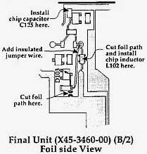
Symptom:
Occasionally an "Hello" message will appear in the display
of the transceiver when the TS-50S is loaded into a antenna without the use of
an antenna tuner. This symptom usually occurs when the negative terminal of the
power supply is floating (un-grounded for RF). This can result in RF feedback
that causes the supply voltage to exceed to 16 Vdc.
Corrective action:
Parts required:
Qty   Description                          Kenwood Part No.  Circuit description
 1    .1 µF chip capacitor                 CK73EB1E104K      C125
 1    10 µH Ferri-inductor                 L40-1001-48       L102
Caution: This modification requires soldering equipment rated for CMOS type circuits. It also requires familiarity with surface mount soldering techniques. If you do not have the proper equipment or knowledge do not attempt this modification yourself. Seek qualified assistance.
Time required for this modification is 30 minutes or less.
23-04-2000 TS-50S Antenna lead
wire
Author: Kenwood
Communication, inc.
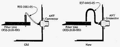
Symptom:
Several users have reported a problem with the antenna
lead connection, i.e. the lead that connects the antenna connector to the Filter
unit (X53-3120-xx). Originally this connection was made by a zero ohm resistor.
If excessive stress is placed on the antenna connector this lead is easily
broken, with a resulting loss of receiver sensitivity and transmitter power. The
use of a small flexible jumper wire will increase the flexibility of this
connection, thus minimizing the effect of mechanical stress.
Parts required:
Qty   Description                              New part No.  Circuit description
 1 Cable                                       E37-0445-05   W2
Procedure:
Remove the zero ohm resistor and replace it with the
small piece of cable. See accompanying diagram.
Caution: This modification requires soldering equipment rated for CMOS type circuits. It also requires familiarity with surface mount soldering techniques. If you do not have the proper equipment or knowledge do not attempt this modification yourself. Seek qualified assistance from your closest Kenwood Service Center (Long Beach, CA, or Virginia Beach, VA).
Time required for this modification is 30 minutes or less.
23-04-2000 TS-50S Mechanical noise from
final unit
Author: Kenwood
Communication, inc.
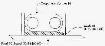
Symptom:
When the transceiver is subjected to vibration a
mechanical noise can be heard from the output transformer area. This has led to
concern by several consumers that something is loose or improperly installed.
Corrective Action:
In order to ease consumer concern toy should add
a cushion under transformer L4 as shown in the accompanying diagram, and replace
transformer L13 at the same time. This transformer has been fastened to the
circuit board with high temperature adhesive, so use caution when removing it
from the circuit board.
Parts required:
Qty   Description              Old part No.   New Part No    Circuit Description
 1    Cushion                  NA             G13-0871-04    (Under L4)
 1    Output transformer       L39-1209-25    L39-1252-05    L13
Time required for this modification is 30 minutes or less.