Modifications for the Kenwood
TR-9000

19-07-1998
TR-9200/TR-9000 Optional Ceramic Filters
FM Adjacent channel
rejection in either unit may be improved by installing an optional narrow
ceramic filter.
Filter    Part No.       -6db Bandwidth -70db Bandwidth Retail
CFK-455F  L72-0304-05    +/- 6 kHz      +/- 12 kHz       33.50
CFK-455G  (CFK-455G)*    +/- 4 kHz      +/- 10 kHz       33.50

* Not original part.  No computer part number.

Location: TR-9200, RX unit X55-1270-10 part, L10
          TR-9000, RX unit X55-1260-11 part, CF1
To install, desolder the original filter and clear the second set of holes
for the optional filter. Solder the new filter in place. Be sure all pins are
actually soldered, and that there are no solder bridges between pins or across
the printed circuit board. Clip the pins flush to the board, and reinstall the
circuit board.
Note: Squelch operation will vary from unit to unit with
an optional narrow filter. Tighter coupling from the detector to the squelch
circuit may be tried to restore "original feel".

19-03-2000 TR-9000
CW, SSB TX instability
Author:
Trio-Kenwood Communication, inc.
Service Bulletin no. 824 (29-5-1980)
Complainte of FMing in SSB, or CW chirp may be eliminated by minor changes to
the TX mixer circuit.
On the TX unit X56-1370-10, perform the following changes:
- Cut the LT foil path.
- Install a 47 ohm resistor on the foil side of the PCB.
- Remove R27, 3.3 Kohm and delete.
- Jumper the cut foil.
- Install a 2.2 Kohm resistor from Q12 Collector to the modified LT foil on
the foil side of the PCB.


19-03-2000 TR-9000 TX
pulse noise in SSB mode
Author:
Trio-Kenwood Communication, inc.
Service Bulletin no. 825 (2-6-1980)
Pulse noise heard during SSB transmission may be reduced or eliminated by
adding one capacitor to the TX unit.
On the TX unit X56-1307-10 add a 22uF 16V radial lead cap to the PMB line, as
illustrated, on the foil side of the PCB.
No adjustment are necessary.


08-04-2000 TR-9000
Transmitter Side Carrier Balance
Author: Trio-Kenwood Communication,
inc.
Service Bulletin no. 849 (30-7-1981)
Distorted sideband transmission may have one of two causes. If normal
alignment docs cure the problem, distortion or poor carrier suppression may be
improved by rercuting two leads in the wire harness.
Perform these initial checks first:
- On early units, ascertain that R74, 47 ohm is on the TX unit X55-1370-10
between connector 33, the LT line, and R27, 2,2 Kohm (vicinity of Q5, Q6), and
that R27 is 2.2 Kohm. (Service Bulletin #824).
- Verify TR-900 Service Manual alignments, General section steps 4 (PLL),
and 5 (HET frequency alignment).
- TX section, steps #4 (power adjustment), 9 (SSB mic gain), 10 (carrier
point) & 11 (carrier suppression).
Procedure:
- Remove the bottom cover and unplug the speaker.
- With the radio upside down and facing forward, locate connectors 8 and 10
at the front of the RX unit X55-1260-00. Connector #8, pin 3 (violet) is the
-6V DC line from the TX unit, connector # 31, pin 1. Connector # 10, pins 7
(signal) and 8 (ground) (green coaxial cable) is the MS pins 5 (sig) and 4
(gnd).
- Carefully cut the cable ties (without cutting any leads) securing these
two lines in the wire harness which runs to the left, around the upright
Control unit, and then right behind the front panel ad far as the Mode switch.
- Carefully unplug each of these connectors by gripping the connector
housing with a long-nosed plier.
- Extract the terminal from the housing by depressing the locking tab and
simultaneously withdrawing the lead with terminal. (See illustration below).
- Reroute these two lines from the behind the Mode switch, between the
chassis and control unit, then left to their original connectors. Reinstall
the terminals in their original positions in the connector housing.
- Coil the excess of each lead and secure with cable ties. Retie the harness
behind the front panel, along the left of the chassis, and back behind the
control unit.
- Readjust carrier suppression. Mod SW:USB, Mic terminal terminated with 470
ohm. On the RX unit, alternately adjust TC1 & VR6 for minimum output at
145 MHz. Carrier should be at least -40dB down.
- Work is complete. Replace the bottom cover.


08-04-2000 TR-9000
Temperature Stability Improvement
Author: Trio-Kenwood Communication,
inc.
Service Bulletin no. 859 (14-4-1982)
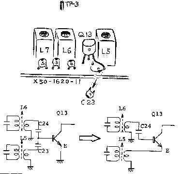
PLL noise or unlock at high temperature may be cured by changing a mixer feed
point in the PLL.
Measure TP3 on the PLL unit. If greater then 0.5V RMS signal is available,
this change will not be required.
If less than this level is present proceed.
On the PLL unit X50-1620-00 at Q13:
- Remove and delete C23.
- Connect Q13 emitter to L5 "hot" (original C23 take-off.)
- Realign L5, 6, 7 for at least 0.5V RMS at TP3.

Note: Installation time for this procedure is ½ hour or less.
Alignment note: To align L6 & 7, first position the slugs flush
with the tops of the coils, then alternately adjust these two coils for maximum
output at the first peak into the coil (fundamental frequency). Then align L5
for maximum.


