Modifications for the Kenwood TM-V7E


19-07-1998 TM-V7E mike & PF1 <> PF4 (1750hz)

                                   TM-V7(E)
                                  ----------

           UP ---+------------------+
                 |                  |
           PF3   +100K+--o/o--------+
                 |                  |
           PF4   +22k+---o/o--------+  
                                    |                      
           8V -> frei/free/libre    |
                                    |
           GND(masse)---------------+--o/o---+
                                    |        |
           DWN---+------------------+        |    
                 |                  |        | 
           PF1   +100K+--o/o--------+        |
                 |                  |        |
           PF2   +22K+---o/o--------+        |
                                             |
           STBY(ptt)-------------------------+---> PTT
                       
           GND(mic)------o/o----
                                  Mic 600ohm
           MIC------------------/

           NC:-> frei/free/libre

 Legende:

        o/o = Schalter oder Taster / switch / bouton ou interrupteur


28-03-1999 Expanding the Kenwood TM-V7: A & E versions

Original TM-V7A Mod from [email protected] (MR CORY B MCDONALD)
Additional TM-V7E notes from [email protected] (Mike Bowyer)


Original TM-V7A Mod:

Remove the top and bottom covers.

Look at the vertical p.c. board behind the front of the radio. There will be 2 small chip resistors on the left side of the board.

Carefully remove the one with the number 0. It will be the one closest to the left near the grounding spring. You will probably have to scrape it off with a pair of needle nose pliers.

After you remove it the VFO ranges should be:
VHF TX 136.995 - 173.995. RX should be 118-174.
UHF TX should be 410-469.995 RX should be 300-470.

Additional TM-V7E notes:

There is a row of five numbered links on the edge of the front panel board.
In my E version radio, 0, 2 & 3 were made as standard. I now have only one link fitted in the number 4 position which enables the repeater function not defaulted in European versions. I have removed all other links.

I can now also receive the AM Aircraft band (118-137MHz). It is possible to change from AM to FM by pressing the MHz button for 1 second. Plus I have discovered doing the same key press (MHz for 1s) in the UHF band gives a 800-999Mhz RX band.

The European version has a 1750Hz tone-burst function, a modified band plan for the auto-repeater shift function, adds a -7.6Mhz repeater shift and sets the band limits to 144-146 & 430-440 - the AM Air band & 800Mhz bands are disabled. All these European 'features' are lost when the radio is expanded.
(The repeater offsets are still programmable, but you must learn how to whistle at 1750Hz). I think the only other difference between the A and E versions is that the E version has an N type antenna connector fitted.

Making link number 5 causes the radio to power up in a Memory recall mode (i.e., with channel numbers) and so is not overly useful!

I'm not sure exactly what links 0, 1, 2, & 3 all do individually! Maybe other configurations are possible: any information would be gratefully received.

As for RF performance, the front-end (and PA) must be tweaked to use frequencies other than the factory alligned defaults, with a little tweaking out of band performance should come good (at the expense of regular 2m/70cm performance).

The chip resistors are SMD zero ohm things - a wire link (or solder blob) will do the same job. They can be carefully removed (for re-use) by using a fine tipped iron, de-solder braid, and a pair of long nose pliers or tweezers. The front board can be carefully detached from the rest of the radio to make removing the links easier.

Mike Bowyer.


02-12-1999 PG-4S programmer cable for the TM-V7x
Author: Wulf, DB8KY


NOTE: This is not a copy of the existing PG-4S cable but a replacement designed by DB8KY.

One of the most handy things about this transceiver is: you can program this transceiver by computer. You can download the software from the Kenwood site but there no datasheet of the PG-4S cable which you require. I found a datasheet which replace the PG-4S cable and is designed by DB8KY. I made this cable and it works fine on my transceiver.

The manual is written in German by DB8KY. He said he never tried this cable on a TM-V7, but it works very good on my transceiver. So here below you will see the instructions.

Have fun! PE1PTS


Der Kenwood TM-G707E ist ja ein schoenes Geraet und die Vergabe von Speichernamen ein nettes Feature, wenn man das alles nur vom Rechner aus programmieren koennte...

Kann man, die Software dazu steht bei Kenwood auf der Web-Seite, dann fehlt nur das Kabel zum Anschluss an den Rechner. Ich habe zwar keine Ahnung was sich in dem original PG-4S Kabel von Kenwood abspielt, wenn man den TM-G707E aber in den Clone-Mode versetzt und sich mal die Signale auf der Mini-DIN Buchse ansieht wird klar, dass es sich bei der Elektronik im Kabel um einen TTL/RS232-Wandler handeln muss. Die unten dargestellte Schaltung erfuellt diese Aufgabe bei mir jedenfalls klaglos. Ich denke das ganze funktioniert auch am TM-V7E.

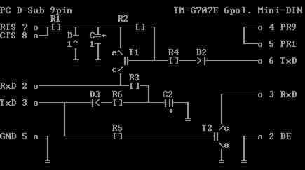
Wie funktioniert es:
Die Verbindung zwischen Pin 4 und 5 benoetigt der Kenwood wohl um von FSK auf seriellen Betrieb umzuschalten. Das Signal vom PC zieht ueber R5 mit T2 den RxD-Eingang am Kenwood low, hier ist intern offensichtlich bereits ein Pull-up

Widerstand vorhanden. Schwieriger ist der Weg vom Kenwood zum PC, der Kenwood gibt nur ein TTL-Signal aus, der serielle Eingang am PC will aber +/- ca. 10V sehen. Also muessen zwei Hilfsspannungen gewonnen werden. Aus dem RTS-Signal
des PC wird ueber R1 eine positive Spannung gewonnen und mit D1 und C1 stabilisiert. Aus dem TxD-Signal des PC wird ueber D3 und R6 dann noch eine negative Spannung gewonnen und mit C2 gepuffert. Dann kann der Kenwood mit den Sendedaten ueber T1 jetzt zwischen der positiven und negativen Spannung umschalten.

Ich habe das ganze in den Sub-D Stecker reingefummelt.
Viel Spass damit wuenscht Wulf, DB8KY
DB8KY @DB0RWI.#NRW.DEU.EU
(Wer das nachbaut tut es auf seine eigene Verantwortung)

PC D-Sub 9pin TM-G707E 6pol. Mini-DIN

pg4s.jpg (5686 bytes)

R1/R6 = 150 Ohm
R2 22 kOhm
R3 10 kOhm
R4 33 kOhm
R5 15 kOhm
C1/C2 = 1uF/16V Elko
D1 = Z-Diode 5,1 Volt
D2/D3 = 1N4148 oder aehnlich
T1 = BC558A oder aehnlich
T2 = BC337 oder aehnlich

For an English Interpretation, visit KC7ZRU's pages. Includes RS part numbers, re-drawn schematic and user comments.