Homebrew
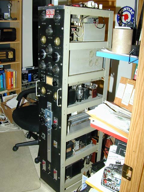 |
This is the beautifully built homebrewed transmitter that I bought a few years ago. Unfortunately the fellow I bought it from can't remember the name or call of the fellow who built it so I can't give anyone credit for it. It uses an 813 for the final and has 2 6AG7's as well as an 807 driver. It had a modulator in it but it was removed at some point in it's life and a tuner was put in it's place. I will have to construct a modulator for it some day but for now it will work fine on CW. I also didn't get any documentation with it so it's going to be a little bit of a challenge to get it running properly. |
 |
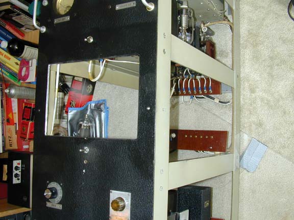
Here you can see the PA plug in coil on top, right above the 813. The 807 is to the right of the 813 and just behind the front panel bandswitch for the driver. Every panel has been cut and finished perfectly. All right angle joints have drilled and tapped blocks for support. This must have taken months of full time work to complete. I will post some more pictures here as I make progress with this rig. There is a seperate VFO of sorts and a crystal switch box which I haven't quite figured out yet. There is also no labeling on the rear panel and a circular MIL type connector is used for the various connections to the outside world. I believe a crystal or VFO should be enough to get it going as there are 2 doublers and an 807 buffer/doubler.
|
 |
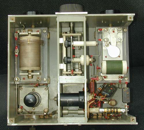
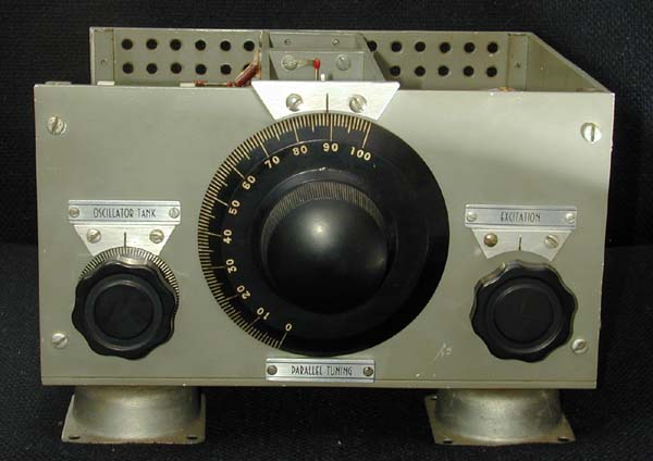
Here is the VFO for the transmitter. I figured it out today and got it going. Works great! Wonderful clean RF output on 3.5, 5, and 7MHz, and when doubled/tripled will give the rest of the HF bands except 160. |
|
|
| And under the hood. Nice construction. It looks better in person. |
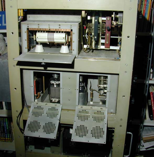
| Well, I dug into the rig on December 6th, did some reverse engineering, placed a wire loop connected to a scope, in the buffer circuit and started playing with the knobs. In about 2 hours I was getting 200W out of it on 75M. Not bad I thought, but only 200W out of an 813 wasn't making me excited. I realized the plate xfmr was only 1500V out and with L drop etc., no wonder the power was 200W. I found a replacement Hammond xfmr with 2350V out which should give me 2000 out under load and 300W at 200mA. It only took 2 more hours to shoehorn the new xfmr into the chassis. See it in the bottom of the chassis on the left side of the picture. The shack is just big enough to accomodate it on it's side. I will wire it on the weekend and then start thinking about a modulator. Probably a pair of 811A's as there is a 1700V tap on the xfmr as well and that should settle at around 1500VDC which will be just fine with the tubes as well as providing lot's of audio for the 813. If you have a modulation xfmr that might work here, 150W or more multimatch and wish to sell it, please send me an email. Thanks. |
 |
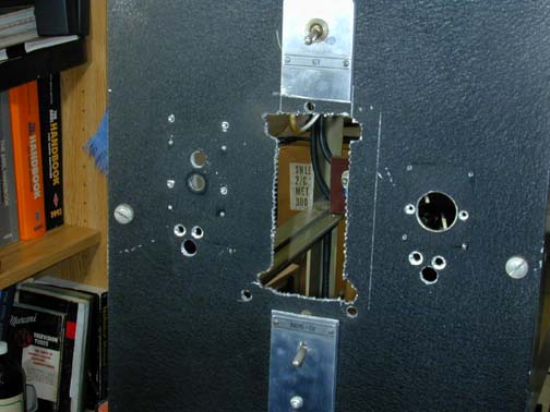 |
Well, the metalwork skills of the previous ower left a lot to be desired. I contemplated how I was going to fill in the holes left from the removal of the tuner. Bondo, aluminum welded in, no, no, no. Then I had a brainstorm, and at the same time decided which modulator tubes I was going to use. Instead of trying to fill the holes, I decided to make a window to view the glowing 813s which I am now going to mount right at the front of the deck, in full glowing glory. |
 |
Now that's better. I will file the edges of the opening to match the other angles on the rig and to set off the window a little. Now to get the deck assembled and get those 813's glowin'.
|

Here is the mod deck, almost done. Just need to finish up the wiring and connect the 6.3V to the 6SN7.
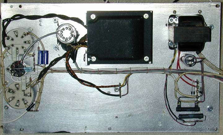
Bottom view of the modulator. Note the waxed wire lacing and attention to detail in matching the original construction style.

|
Ahhhhhh. Fire in the wire. Those 813's are hard to beat for visual appeal. I now have 2000VDC applied and will try modulating tonight. Well, after 1 week of playing with various parameters on both the PA and the modulators, I am now happy with it's performance. I have quizzed many minds and read lot's of data books and handbooks and have come up with a good combination of voltages and currents that give good modulation and output power. |
Here are the specs.
|
PA SINGLE 813
|
MODULATOR PP 813's |
||
| 1500 VDC Plate supply for modulator and PA | 50 mA idle 250 mA max signal | ||
| 340 VDC on the PA screens through a 50K dropping resistor | 690 VDC seperate supply on modulator screens | ||
| 200 mA in the PA 813 | |||
I tried the handbook recommended method of modulating
the tetrodes but I was unable to get +100% modulation with the PA screen connected
to a dedicated supply though a 10H choke. My modulation xfmr has a turns ratio
of 1.49:1 which might not be quite right for this application. 1.6:1 might
be a bit better but I haven't been able to locate one yet. With the above
parameters the transmitter puts out 200W and greater than 100% positive peaks.
One important note is that the AC suuply to the shack had to upgraded. When
the transmitter was keyed and modulated, the line voltage sagged to 107VAC.
I split the 240VAC from the Bauer TX and now supply the 813 rig with a solid
120VAC line. It made a big improvement
Back to the Main Page