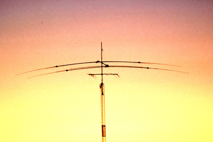
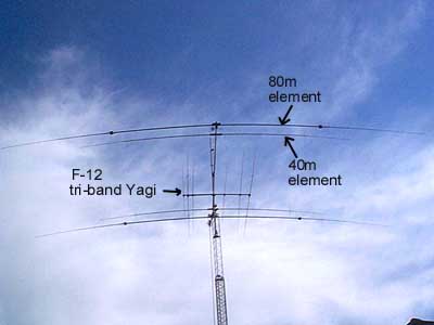
80m & 40m DUAL BAND HOMEBREW 2 EL SHORT BOOM YAGI

RECENT UP-DATE:

 IN THE SUMMER OF 2018 THE 2 EL 80-40 YAGI FEED SYSTEM WAS RE-DESIGNED TO ALLOW FOR INSTANT 180 DEGREE DIRECTION SWITCHING.  THE 4NEC2 MODELING, ELECTRICAL DESIGN OF THE SWITCHING SYSTEM AND LUMPED LC MATCHING NETWORK IS EXPLAINED IN A PAPER FOUND HERE: 80M YAGI

ALSO EXPLAINED IS A DIFFERENT METHOD FOR TUNING ANY 2 EL YAGI FOR MAXIMUM PERFORMANCE WHICH IS EASIER AND MORE RELIABLE THAN THE METHOD DESCRIBED HERE ON THIS WEBSITE.

THIS YAGI IS STILL IN SERVICE AFTER 17 YEARS OF USE. THIS WEBPAGE REMAINS RELEVANT REGARDING MECHANICAL AND COIL DESIGN.

PLEASE VISIT MY QRZ.COM PAGE AND YOUTUBE CHANNEL FOR MORE UP-TO-DATE INFORMATION ABOUT THE VE6WZ STATION

Follow the links at the left to see various pages of design and construction details. (Click to see a full size photo of the Yagi)

Click here to see a view looking from the end of the Yagi at 100'

The VE6WZ QTH is a small city lot, so achieving gain on 80m has been difficult.  A vertical 4 sq. wire array  was considered but would have been a compromise design because of the crank-up tower and limited space.  The surrounding ground clutter and variable terrain would have made vertical performance questionable.  Good DX results have been experienced using the Force-12, EF-180B, 80m rotatable dipole at 100' so it was decided to design a 2 el 80m yagi around similar elements.  (F-12 markets such yagis).  The VE6WZ yagi design uses high Q "mostly air core" loading coils instead of the linear loading on the 68' elements.  Because of dimensional constraints at the VE6WZ city QTH, a 28' short boom reflector design was built with the 2 el 40m yagi sharing the same boom.

(Here is a very shaky video taken with an iPhone showing the TX antenna install at VE6WZ. There have been a number of questions regarding the crank-up tower and 160m shunt feed, so this video tries to answer them: YouTube video )

See Performance page for more Polar Plots

Above: Field measured azimuth plot of the Yagi on 3.8 and 3.793 MHz.

80m 2 el Yagi specifications

Max F/B:                                        20 dB peak  (10 dB within SWR bandwidth)

Max gain:                                      8.95 dBi (at 100', 33 deg ele. angle)

2:1 SWR bandwidth:                     26 kHz (with switching 55 kHz) 3810-3760, 3550-3500.

Feedpoint impedance:                   15-20 ohms (hairpin match- split element)

Longest element:                          66'

Boom :                                           28' (2-1/2" X  .125) Trussed

Weight of 80m only:                     170 lbs

Weight total with 40m elements: 210 lbs

Estimated windload:                     13 sq. feet


Listen to the directivity of the Yagi on 80m:

 In this QSO with Jose, F5JD at first the Yagi was pointed at 90 deg. with very poor copy. Part way through the recording the beam is rotated to direct path at about 40 deg. and the copy is Q-5. This IS NOT a F/B test...the beam is only rotated about 50 deg.   Click here and your sound player should play this .mp3 file: F5JD_80m-03-10-12.mp3

 More sound recordings can be heard on the Sound File Page.


Does it work ??  DX Performance......

Working DX is not proof of good performance, but since the Yagi was installed, DXCC has been worked every year on 80m (starting from zero in September). Best DXCC per 7 month season:  80m- 168 countries, 40m- 210 countries.


Each winter season during the 7 month period from Sept. to Mar. DXCC has been worked on 80m. 

Here are the past 80m VE6WZ annual results: 

2002-3:   112 countries

2003-4:   111 countries

2004-5:   111 countries

2005-6:   140 countries

2006-7:   136 countries

2007-8:   156 countries       On November 24, 2007 reached 105----80m DXCC in 84 days

2008-9:   162 countries       On November 21, 2008 reached 101----80m DXCC in 81 days

2009-10: 165 countries       On November 10, 2009 reached 100----80m DXCC in 70 days

2010-11: 168 countries       On November 26, 2010 reached 109----80m DXCC in 86 days

2011-12: 126 countries       On January     26, 2012 reached 101----80m DXCC in 148 days

2012-13: 134 countries       On December 31, 2012 reached 100-----80m DXCC in 120 days

2013-14: 115 countries       On December 12, 2013  reached 100----80m DXCC in 110 days

2014-15:   92 countries       A poor low band DXCC season.       ----80m DXCC not worked

80m DXCC total using the Yagi beginning in 2002: 293 countries confirmed

40m DXCC total using the Yagi beginning in 2002: 336 countries confirmed

(VE6WZ DXCC totals here)

What does a pile-up of 80m EU DX sound like at VE6WZ ? (this sound file is a recording of a great 80m SSB opening): http://www.qsl.net/ve6wz/VE6WZ_80m_pile_05-12-24.mp3

(If you are from the East coast USA, the above file may not seem that impressive.....EU DX from the west coast can be a challenge)

A 7 year statistical analysis of 80m DX data from VE6WZ: click here

Compromised performance issues (80m):

This Yagi is almost one half  full size on 80m and is a great DX performer. It has about 1 dB less gain but shows better F/B than a design using full size elements (see here).  The small size makes it feasible to install in many situations where a full size monster would not be possible.....however some performance and operational issues arise:

1.)    This would NOT be a great contest antenna because of the very narrow bandwidth and requirement to use switching to move around the band.  The bandwidth could be expanded by retuning the reflector to sacrifice some gain, but some switching would still be required.

2.)    The large coils are susceptible to inductance change when covered with snow, ice or frost.  In severe cases this can render the Yagi unusable.

3.)    Because of the narrow bandwidth and tight coupling of the elements the SWR will "swing" during windy conditions as the elements move.

4.)    The narrow bandwidth and close coupling of the elements makes tuning critical.  Great care and effort must be taken to adjust the elements for best performance.  On the tower, field testing will almost certainly be required to get the tuning right.  WARNING...This is not a "plug-and-play" design.  If you build this design be prepared to spend much time tuning the elements for optimum performance.

(see here for comparison plots to a full size design)


WHY INDUCTOR LOADING ??


Low loss loading coils-
      6" dia, 6" long 1/4" copper tubing

VE6WZ displays one of the 80m loading coils.

The Cushcraft "shorty-forty" experience.....

The Cushcraft XM-240, 2 el  40m yagi has been used at VE6WZ for 3 years.  It has 43' inductor loaded elements mounted on a 22' boom. The loading coils are 68 turns of 12 ga. wire close-wound on a small diameter (3/4 inch) fiberglass form. Other sources have indicated a coil loss of around 3 ohms, and software calculations indicate a loss of up to 8 ohms !! (see photo of the Cushcraft coil). The coils are placed about 61 % out from the center along the element half length. The split element is fed directly with 50 ohm coax through a 1:1 balun. In spite of these poorly designed lossy coils, this yagi is a proven performer. The thesis is that an 80m design using well designed high Q coils should perform well.

The Force 12 linear-loaded 80m dipole experience......

The F-12 80m dipole (EF-180B) is a 68' long, linear loaded element and has performed well at VE6WZ for two years. The linear load wires extend from the mid-point of the half element inward toward the element center. The wires are aluminum clad 12 gauge steel wire. The split element is fed with 50 ohm coax in combination with a "helical hairpin" to match the 18 ohm feedpoint. MININEC was used to model an 80m dipole using 68' elements and lumped inductance (coils) at 50 % from center. The feedpoint impedance is calculated at around 32 ohms. This is almost double the 18 ohms realized when using linear loading where the wires come in toward the feedpoint. Others have explained that this low impedance is because the "effective" load point is moved inward toward the center due to the loading wires running inward along the element. A low feedpoint impedance will tend to decrease efficiency.  Tests on the tower support the 32-ohm feedpoint using low loss (high Q) coils.  The 2el yagi design using 18 ohm linear load elements would end up with around a 10 ohm feedpoint !!!! due to mutual coupling. This could greatly degrade efficiency. Modeling the 2 el inductor loaded design yields a reasonable 16-20 ohm feedpoint. The total wire length used in the coils is much less than that needed for linear loading, and the .25 " copper tubing used for the high Q coils has less resistance than the 12 gauge AL clad wire. The element connection points can introduce further resistive losses and these are minimized at the coil-element connections by implementing electrical redundancy.

NEXT......Design and modeling

Below...the Yagi at 100' at sunrise.

The Yagi at sunrise