|
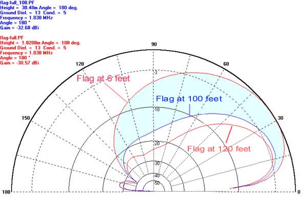
This model shows how the high angle lobe becomes depressed when the flag is raised from 6 ' to 100' and 120'. Notice that the gain is down slightly, but much high angle noise will be suppressed (shaded blue). This high angle suppression is at a maximum at 125', after which a higher angle lobe starts to develop. This looks like it could be a very good rotatable RX antenna. A three-quarter scaled version could be built easily rotatable to be placed on top of a TX tower and used with the appropriate pre-amps. The tower MUST BE DE-TUNED since modeling shows that the pattern is destroyed when a resonant antenna is near-by. Full size flag model (14' high by 29' long) 1.830Mhz. The pattern for this antenna on 3.5 Mhz is very poor at 100' and 120' because of a very nasty high angle lobe. Optimum height for a 3.5 Mhz Flag is 1/4 wavelength.....around 61'. see here 80m Model It is possible that modeling using a NEC based program may show some different results since the 6' model is close to the earth. ( I expect the gain difference may not be as great since MININEC apparently does not account for earth losses when wires are close to the ground.) |
 |
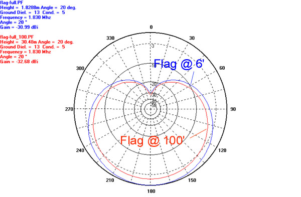
| This shows the Azimuth plots (at 20 deg.) of the 6' and 100' models. Not much change in the pattern with increased height. Too bad the forward lobe is not more narrow..... it could start to look like a Yagi pattern!! |
 |