AVR Thermostat
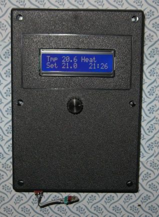
This thermostat is built around an ATMega164 and a TC1047A temperature sensor. It controls your furnace and air conditioner. It is not programmable, although it has a clock and is capable if some additional code were written (any volunteers?). The unique feature is that instead of a bunch of buttons and switches, I used a single pushbutton rotary encoder, for a very simple user interface.
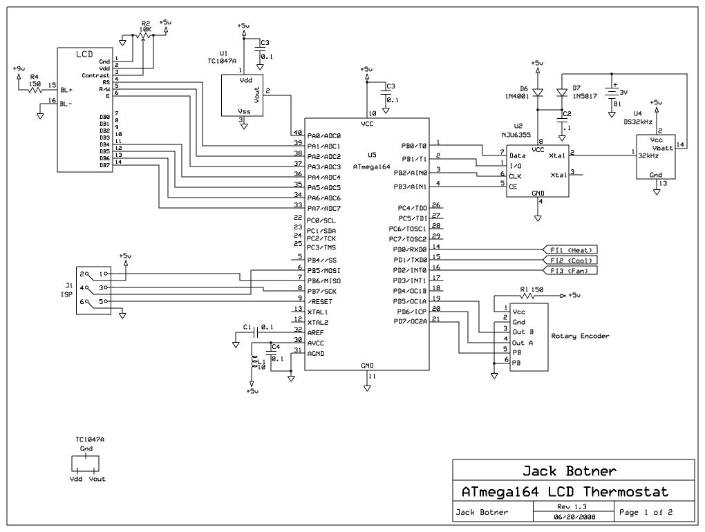
The ATmega164P has plenty of I/O and memory. The LCD is the usual 16x2 parallel I/O. The TC1047A temperature sensor is easy to program to, if you don't mind its tiny size. The real time clock is a NJU6355. Note the use of a DS32khz instead of the usual 32 kHz crystal; I was fed up with RTCs running a bit fast or slow, and I wanted to try this as a possible solution.* Finally there's the rotary encoder; I used a Grayhill Inc p/n 62P22-L4. The Digikey part number is GH7295-ND, and the price was C$4.69. (More information on this part can be found on my rotary encoder page.) The encoder outputs a 2 bit code which allows you to tell if it is being turned clockwise or counter-clockwise. In addition it has a pushbutton built in to the shaft.
The most interesting part of this project is the use of the rotary encoder. In run mode, turning the knob raises or lowers the temperature setting. Press the button and you enter the customization menu. The first menu lets you select heat, cool, or off. The next menu lets you turn the fan on or off. After a few more menus you can set the clock if you like, then the unit returns to the run mode again.
The nice thing about this thermostat is that it is powered by the furnace. There are no batteries to replace. The last set temperature is remembered in EEPROM so it always returns to the correct state after a power off. What I really like is keeping the LCD backlight on all the time, since there is no need to conserve power.
To make this possible you need access to the "C" wire in the furnace, which is not normally run to the thermostat. My thermostat had "RH" and "RC" wires which were both connected to the "R" terminal in the furnace. All I had to do was move one wire to the "C" terminal (the unused one!).
You may find the terminology of the thermostat/furnace connections confusing, I certainly did. I am not in the heating/AC business so my knowledge is based on study of the furnace schematic and my own speculation. The furnace contains a 24V transformer which powers the control system. One lead of the 24V secondary is common/ground and called "C". The hot side of the transformer secondary is called "R". "R" is delivered to the thermostat which contains one to three switches to activate the functions of the furnace and A/C. Each switch requires one wire back to the furnace controller. The one switch all thermostats have is heat, which is returned to the "W" terminal in the furnace. If you have A/C, the cool switch returns to the "Y" terminal. Finally if you have a Fan On switch, it is returned to the "G" terminal.
There may be other kinds of furnace control systems in use. Please make sure your furnace corresponds to my description before you try it. You could damage your furnace controller. I cannot be responsible.
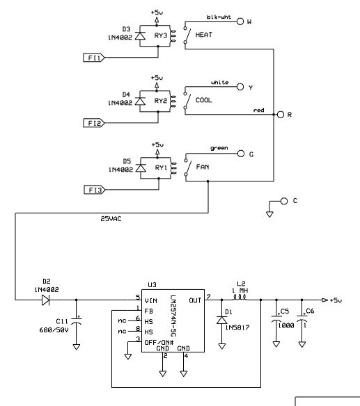
In order to get power from the furnace I accessed the 24 VAC across the "C" and "R" terminals, rectified by D2, filtered by C11 and regulated by U3**. My switches are relays, RY1 RY2 and RY3. I happened to have a few SPST reed relays that operate at 5V and 10 mA, so they can be driven direcly from the AVR I/O port. These relays are labelled "Hamlin HE321A0400 8006". I rescued them from an old PCB many years ago. (The Fan On relay has been energized in my project for years now and still works!)
J1 (in-circuit programming connector) was used during development but you can leave it out if you like.
Thanks to Peter Fleury for the
AVR LCD routines.
On the left photo, the ATmega164 is hidden directly under the LCD. The 3 LEDs to the left of the rotary encoder are not necessary and do not appear on the schematic.
Looking at the (right) photo of the bottom of the circuit board, there is a small board plugged in to where the furnace connector goes. This board lets me supply power to the unit from a wall wart, and has 3 LEDs to tell me when any of the 3 furnace relays are on. This was used for development and testing. The ISP connector is at the top left, and the temperature sensor is at the bottom right. Keep in mind that the regulator dissipates some heat, so you have to keep the temperature sensor away from it. (The 7805 has been replaced with a LM2574N, so there is very little heat now.**) Mine sticks out of the bottom of the box.
Oh yes, the temperatures are shown in degrees C. A minor code change would be required to show temperature in degrees F.
Regarding the ATmega164P fuses, the internal clock is used. The ony fuse requiring comment is the brown-out detect, which I now enabled to the 4.3V setting. I used this unit for a year with no brown-out detect and no problem, but then suffered a series of brief power drop-outs over a few days, and the unit hung twice. Hopefully the brown-out detect will cure that.
Download C source code for AVR Thermostat
* Update on the DS32khz: it really works, although I can't quantify it precisely. The clock appears to keep good time (within a second or two) after a few months in operation.
** Update 07/08: I replaced the 7805 regulator with a LM2574N. Since the input voltage was pretty high (around 35V) and the current around 150 MA, the 7805 was getting pretty hot (4-5 watts). The LM2574 is a switching regulator and barely gets warm. The only trick is using the correct inductor for L2. I am not a big fan of toroid cores, since I have a box full of them and don't know what most of them are. Still I decided to wind my own inductor. First I tried one core that required around 40 turns to give 1 mH. When I tried the circuit, the LM2574 got hot as blazes! So I tried another core, rescued from an old PC switching supply, and found it needed 300 turns for 1 mH. This time the circuit worked perfectly, with very little heat. I used #24 wire, although #26 should be OK too. I think that the 1st core was ferrite and saturated at too low a current, dropping the inductance drastically, overworking the poor LM2574. The 2nd core must be iron, just what was needed. A good clue is that ferrite cores require a lot less turns than iron, although the mix and frequency would have some effect on that, etc. etc. My old ARRL Data Book has some information on toroid cores, but not what I should do with my box of unknowns. The ON Semiconductor spec sheet has some very useful information on selecting the inductor and other components.
An article in QST March 1994 by WA8MCQ says, ".... home-brewers quickly learn to assiciate core color with certain characteristics. For example, a red core is type 2, with an initial permeability of 10, and yellow is type 6, with a mui of 8. Although we may think we know this color code well, there are times that it can backfire on us. Let's say you're at a hamfest and see a box full of surplus cores ..... Since they are a certain color, you assume you know what they are ..... you might be in for a nasty surprise. The problem is that the color code we know is only used by a few manufacturers; there is no universal color code for powdered-iron and ferrite materials. ...... Let's say you come across a red core of unknown origin. Depending on who the manufacturer is, it could be the familiar type 2 powdered iron core with a mui of 10; but it could also be a ferrite core with a mui of 850, 1800 or 10000. .... So be suspicious of a colored core if you don't positively know who made it .....".