Memories
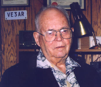
By Bill Loucks, VE3AR
(VE3BDB Note:
Bill Loucks has had an interesting life and career, including during World War
Two where he was involved with various military communications and electronics
gear such as the WS#19. We are grateful to him for
providing this exclusive account.)
©Copyright
Recently while sorting my old
files I came across my first ham license, dated 30th April 1936,
nearly 70 years ago. This brought back a flood of memories which I now share
with you.
Look at the frequency bands on
my license (thumbnail at bottom of page). Notice that most are broken into segments.
This allowed Advanced Amateurs (who required 2 years operation as an ordinary
Amateur plus further code and theory tests) to have their licenses endorsed
for phone operation by typing telephone after C.W. against the appropriate
frequency range. Phone frequencies then were 1750 - 2000, 3500 - 3550, 3850 -
4000, and 14100 - 14300 kHz, with no phone on 40 meters. Interestingly, we
had our own exclusive Canadian phone on 3500 - 3550 kHz, and CW both below and
above the 20 meter phone band.
Look also at the number on my
license, 1807, perhaps meaningless in itself but suggestive of something
interesting. The number on my Certificate of Proficiency in Radio dated 7th
April 1936 is 3354. These were introduced in 1922 and numbered
sequentially. Dave Lloyd ex VE3AW held number 1, which now hangs on the wall
of current VE3AW, the HQ station of the CNIB Amateur Radio Program which he
founded in 1967. Taking into account Silent Keys from 1922 to 1936, ham
population in Canada in 1936 was about 3000.
Another interesting item:
then we had 5 meters, 56 to 60 MHz, not 6 meters at 50 to 54. When amateurs
came back on the air following WW2, it was apparent that TV would be the next
big frequency user. The authorities set aside 13 channels for TV stations.
Channel 2 was from 56 to 62 MHz taking over our 5 meter band. But to keep
hams happy, they temporarily gave us 4 MHz of channel 1. Now 60 years
later we still have channel 1, which is why TV channel numbers begin at 2!
Canada was divided into five
call districts: 1 for PEI, NS and NB, 2 for Quebec, 3 for Ontario, 4 for
Manitoba, Saskatchewan and Alberta, and 5 for BC , Yukon and NWT. Also, VE9
calls were for truly Experimental Radio Stations beyond and above Amateur
Experimental Stations. They could operate in the ham bands, but usually also
were given other frequencies. Alex Reid VE2BE, one of the originators of the
Canadian Division of ARRL and its first Director, held VE9BE. I never managed
to work a VE9, but others did.
Call signs in the US also had
their peculiarities. There were only nine call districts - no zero. Suffixes
beginning with X were assigned to broadcast stations since short wave
broadcasting still was considered experimental. KDKA in Pittsburgh, one of
the first short wave broadcasters, had the call W8XK. Suffixes beginning with
Y were assigned to schools, mainly club stations at universities.
Occasionally a W0 call would be assigned to a station hard to classify. I
have an SWL QSL card from a W0 flying across the States in a balloon. In both
Canada and the US, one had to get a new call sign on moving from one call
district to another.
We were called The Amateur
Experimental Service both internationally and nationally. Our purpose in the
scheme of things was primarily "Self-training". And that it was. Practically
everyone designed and built his own equipment. I started with a one tube
transmitter using a type 45 triode which had a plate dissipation rating of 10
watts (250 v at 36 ma). I used a TNT oscillator circuit, which as the name
suggests, was dynamite. The more usual circuits were TPTG (tuned plate tuned
grid) and HARTLEY.
The TNT tuned only the pate
circuit. Meters to tune up by were expensive, and many of us did not have
one. We used a pilot lamp hooked to a one turn loop of wire having the same
diameter as the tank coil, held close to the tank coil and tuned for maximum
brilliance. To check for RF we held a neon bulb close to the circuit or drew
an arc with a lead pencil.
Eventually I bought a
milliammeter, the cheapest available. This was a moving vane type, not the
respected moving coil type. Inside was a permanent magnet and a magnetized
vane connected to an indicating needle. A small coil of wire near the magnet
carried the current to be measured. Its field altered the total magnetic
field affecting the vane and the needle would move. Very cheap, but also very
vulnerable. The first short circuit demagnetized the permanent magnet and the
meter was useless. I went through several before I could afford a moving coil
meter. (Don't forget those were the "dirty thirties" and I lived in probably
the hardest hit part of Canada.)
We had only diode, triode,
tetrode and pentode tube types then. The tetrode was a great advance, not
needing neutralizing when used as an RF amplifier. Usual transmitter circuits
required an A power supply for the filaments, a B supply for the plates, and a
C supply for the grid bias. But there was a zero bias receiving tube, a type
46, which I used in a later rig consisting of a 47 pentode oscillator and a
pair of 46s in a push-pull zero bias final. Key-up plate current was not
zero, but was a small fraction of key-down, and the tubes did not overheat.
This saved making a C supply.
Tubes in those days did not have
a cathode and heater. They had a filament just like that in a light bulb,
which functioned as the electron emitter or cathode. But a hum would develop
if one side of the filament was grounded to provide the return path for the
plate current. So, the filament winding on the power transformer had a centre
tap to provide a balanced ground connection. Filament voltages of receiving
tubes were 2.5 volts at currents as high as 2 amps.
Developed a bit earlier, but
still commonly found in transmitters in 1936, were triode tube types 203, 210
and 211. The 210 had a rated plate dissipation greater than receiving tubes
(forget how much), and the 203 and 211 were 50 watters. A typical QRO
transmitter was a 210 driving a pair of 203s modulated by a pair of 211s. Also
around in those days were the vintage 171 tubes of battery radios used before
the Roger's Battery less was invented (call letters of broadcast station CFRB
come from Rogers Battery less), and the first miniature tube called a peanut
tube. The peanut tube was used in hearing aides - not the kind you put in
your ear but the kind you carry on your shoulder.
Operating styles were quite
different pre-war. Transmitter frequency control was primitive, initially
with self excited and later with crystal controlled oscillators. Crystals
were expensive. The tri-tet oscillator permitted output on the fundamental or
second harmonic, thus covering two bands with one crystal. Crystals for
frequencies above 4000 kHz were scarce and costly. So, to get on 80, 40, 20
and 10 with one crystal we used a tri-tet oscillator followed by a doubler
stage.
Since frequency was fixed, only
by luck could both stations be on the same frequency. When we called CQ, we
would start listening at the bottom of the band and slowly tune higher until
hopefully we heard a reply. This could take some time, so when one answered a
CQ one called for a long time, up to a minute, before signing. That is what
made break-in, QSK, popular. Using frequency multipliers simplified the rig
but also produced some strange effects. I remember one QSO on 40 with a chap
about 20 miles away when it suddenly occurred to me that he may not be
operating on 40. I asked him, and he was transmitting and receiving on 80.
He was copying my oscillator before doubling and I was copying his second
harmonic. My first cross band QSO.
My receiver in 1936 was a home
built version of the National SW-3 having a T R F, a regenerative detector,
and an audio stage, and of course used plug-in coils and earphones. Soon I
added a power output stage to run a speaker. Simple, but effective. I even
worked several VKs on 40. In the winter of 1938 - 39, I designed and built my
first superheterodyne receiver, a sooper-dooper affair, constructed around a
commercial 3 stage, 5 band turret tuner covering 550 kHz to 30 MHz
continuously.
It had mechanical band-spread
using a dial with a 140 to 1 fine tuning ratio. It also had an IF crystal
filter using a crystal from a National HRO, and an IF Lamb noise silencer.
The noise silencer proved invaluable, not for silencing noise but for
silencing the receiver during keying. We had no fast acting relays nor vacuum
tube T/R switches. We used a knife switch or conventional relay. Most of us
did not switch the receiver off and just put up with the thumping from
keying. The Lamb noise silencer silenced the receiver during keying.
When WW2 came along, the
"self-training" of the Amateur Service came into its own. All licensed hams
in 1939 received an invitation to join the RCAF because of the skills
developed as hams. At the time I was enrolled in engineering at the
University of Saskatchewan in Saskatoon, and we were asked to stay at school
and complete our degrees. I stayed, but was able to contribute to the War
effort during summer vacations.
In 1940 I worked on the survey
party that laid out and supervised the construction of Number 32 Service
Flying Training School (S F T S) just south of Moose Jaw, as chain-man,
rod-man and eventually instrument-man. In 1941 we extended the runways and
taxi strips. This airport still is in use 65 years later, now called C F B
Moose Jaw and home to the illustrious Snowbirds.
In 1942 I worked at the
Northern Electric plant on Shearer Street in Montreal, on the production of
the Number 19 Wireless Set for tanks. It consisted of three separate units on
one chassis, an HF transceiver (A Set), a VHF transceiver (B Set), and an
intercom (C Set) and was produced on an assembly line of about 120 operators.
After every fifth operator an inspector checked the work in progress, plus a
final check and live test at the end of the line. I started as a line
inspector, but in a week or so was moved to final inspection. My ham training
enabled me to quickly locate and repair faults in the sets. All sets had
markings in the Russian language and were destined for the Russian Army.
(In a later message, Bill advised:
Yes, I remember Syd Sillitoe, not as a friend
but as the engineer in charge of #19 production at
Northern. His recollections I am sure far outdistance mine. I have
little to add other than it was the first HF transceiver I ever encountered,
and really was amazed at how it was done. It took many years for the amateur
community to adopt transceiver technology.)
I graduated in Engineering
Physics in April 1943. A month before graduation I joined the RCNVR, the
"Wavy Navy", along with my six classmates in Engineering Physics. After
receiving five months training in naval basics, radar theory and radar
practice, I was posted to Signals School at Saint- Hyacinthe, Quebec, to teach
Radio Artificers the intricacies of naval radar practice. All Radar Officers
held commissions in the Special Branch of the Navy and wore a light green
backing under their rank stripes. So did Laundry Officers, Bandmasters, and
other odds and sods. So, to recognize their special value, all Radar Officers
were reclassified late in 1943 as Electrical Branch and wore a dark green
backing.
The Canadian Navy began training
Radar Officers in 1940, one class a year usually of 20 to 30 fresh university
graduates in engineering or physics. They were NOT for the Canadian Navy.
All graduates of the classes of 1940, 41 and 42, and half the class of 43,
went to the British Royal Navy. As a graduate of class of 43, I was asked if
I wished to go to the Royal Navy and said it didn't matter, wherever I was
needed. I stayed with the Canadian Navy. All of the class of 44, the final
class, stayed with the Canadian Navy.
Initially we were not called
Radar Officers, for the Allied navies did not have radar - they had RDF. A
short time after WW1, navies had radio Direction Finding or DF
equipment. When radar came along it was viewed as an extension of direction
finding to include range as well as direction and hence the name Range
and Direction Finding or RDF. It was not until the Yanks came
into the War that the term radar came into use.
After a year at Signals School I
was posted to sea as a Group Radar Officer for an escort group of six
corvettes on convoy duty in the North Atlantic. Each ship had two sets, the
older SW-1C VHF Canadian set, popularly called The Swick, operating I believe
around 180 MHz and using a yagi antenna with manual rotation, and the new 3
GHz British set using a parabolic slice antenna also with manual rotation, and
of course the VHF IFF (Identification Friend or Foe) transponder continuously
sweeping the range of frequencies used by VHF radar, 50 MHz or more, using a
broad band vertical antenna.
The IFF would automatically
respond to any incoming radar pulse with a coded reply giving its own
elongated pulse(s) on the tail of the reflected pulse to identify the target
as friend. Both the VHF and early microwave sets used coax feed to the
antenna. This consisted of copper tubing about half an inch in diameter
filled with an anhydrous compound, I believe magnesium oxide, which sucked up
water like a sponge. The first thing one suspected when echoes began to get
weak was water in the coax. The repair was simple. Use a blow torch to boil
out the water, starting 4 or 5 feet from each end and progressing to the end.
The VHF antenna was mounted on top of the mainmast requiring a frightening
climb.
Radar of course produced echoes
from waves as well as from objects in the waves such as a submarine
periscope. While at sea I came across the circuit of a British device to
reduce wave clutter, and decided to build one. It worked fine, so I sent a
letter describing the device to my former boss at Signals School and set off
to sea again. When I next hit home port I was met by the RCMP, telling me in
no uncertain terms I had breached national security by putting highly
classified information in the regular mail. (It was caught by the universal
censorship we had in those days.) I was properly chastised. On my next
return to home port I found waiting for me a Commendation from the Admiral.
After VE Day I was no longer needed at sea and was transferred to the newly
created Canadian Naval Radio Laboratories at Saint-Hyacinthe. My first
assignment was to build anti-wave clutter devices for all Canadian naval 3 GHz
surface warning radar. Guess the self-training objective was met.
On discharge from the Navy I
took up the veterans' benefit of further education, and enrolled in a Masters
in Radio Physics program at the University of Western Ontario in London. By
then I had a wife and daughter to support and needed more money than the
Government granted, so became a lab demonstrator in physics during the winter
term, and was given a summer job working for the Department of Medicine. My
assignment was to design and build a device to record the instantaneous heart
rate. This I did, and the work was published in the NRC Journal of Research
under the title An Instantaneous Recording Tachometer for the Study of the
Human Autonomic Nervous System. Again, my thanks for the self-training of ham
radio.
My thesis was to be based on the
correlation between optics theory and radio theory, particularly the
phenomenon of diffraction which occurs when light passes over a sharp edge.
Physics labs demonstrate the effect by passing light through a pin hole and
showing the resulting rings on a screen, using a setup known as an optical
bench. At microwave frequencies, a parabolic reflector antenna virtually is a
pin hole, and spurious radiation can cause confusing side echoes. The
Canadian designed RXC, 3 GHz (10 cm), naval radar built by government-owned
Research Enterprises Limited in Leaside had such an antenna and was almost
useless because of side echoes. Sea trials of RXC were done on one of the
ships in my group before I took over, and in spite of a disparaging report by
the Radar Officer who conducted the tests (also one of the 1943 class), the
set was still in service. I believe only two or three were ever produced.
Research Enterprises became Philips Electronics after the War.
Being used to home brewing, I
set out to make a radio light source, a radio pin hole, and a radio optical
bench to determine experimentally if the diffraction of radio waves followed
the diffraction laws of optics. I used a type 723 klystron, the local
oscillator tube of 10 GHz (3 cm) radar, driving a wave guide horn antenna to
illuminate a wall of copper mesh about 20 by 20 feet with a 3 foot pin hole in
the centre, and an optical bench of another horn antenna, this time feeding a
crystal detector commonly used in radar, all erected on the back campus. The
contraption worked like a charm, again thanks to the self-training of ham
radio.
I joined the Research Division
of Ontario Hydro in May 1947 and specialized in distribution and transmission
of electricity. This started off with grounding for safety to life and
property, including lightning protection. We needed to know more about
lightning to properly design protection systems. I was given the task of
designing and building a device to count the number of individual strokes in a
single bolt of lightning. I came up with an electronic counter triggered by
the electrostatic field picked up by a small antenna. It worked well - too
well, for it was counting strokes from miles around. We added a visual gate,
a photocell, to require both the electric field and a flash of light to
trigger. Again, ham radio to the fore.
Scads and scads of war surplus
electronic gear came on the market in the late 1940s, much to the delight of
hams. In Toronto Yonge Street just south of Wellesley became the home of most
vendors. Alongside the surplus vendors was a small store selling regular
electronics, not surplus - Electrosonic. Our shopping habit took us first to
the surplus stores, and if (rarely) we could not find the part we needed
there, then to Electrosonic and pay the regular price.
One surplus store in particular
was overflowing with gear - receivers, transmitters and power supplies. To
move them faster, this store had auctions every so often, and of course I
frequently attended. I came home one time with three Marconi B-28 naval
receivers for only $7.00. They had a 230 volt power transformer and as I
recall covered 60 kHz to 18 MHz. The valves were British, the EF series. On
two B-28s I replaced the transformers with Hammond 115 v units and all valves
with modern Canadian tubes. Both sets worked fine.
Then I completely rebuilt the
front end of one to convert it to ham bands only. Again it worked fine and I
used it for some time. I sold the third unmodified unit for $7.00. Another
time I came home with two fully operational massive power supplies. They used
a pair of mercury vapour 866s to give 500 v at 500 ma, a mercury vapour 83 to
give 200 v at 100 ma, and a huge copper oxide rectifier stack giving many amps
at up to 24 v as determined by the setting of taps on the power transformer.
I used one for several years to power my home brew transmitter. You should
have seen the flashing blue lights when I keyed! Also, crystals for frequency
control were dirt cheap, but of course ground to military frequencies.
Several entrepreneurs sold
crystal kits containing mounted crystals in the 6000 to 7000 kHz range and a
package of grinding powder. All one had to do was swipe the quartz wafer a
few times across a piece of plate glass coated with a water mixture of the
grinding powder. If one took too many swipes and its frequency was too high,
one used graphite from a soft lead pencil to lower its frequency. Net cost of
a 40 meter crystal was about a dollar.
TV reception in Toronto began in
the early 1950s when two stations started broadcasting from Buffalo, channels
2 and 4. And all hell broke loose for hams. The second harmonic of 10 meters
and the fourth of 20 fall in the middle of channel 2. Until then, no one
worried much about harmonics. During the Sweepstakes Contest just after TV
reception started, I was busily racking up points when the phone started
ringing, the door bell began clanging, and people started banging on the
window of my basement shack. They demanded that I stop transmitting (there
was some special program on TV). Being young and egregious, I continued
racking up points. The next day a Radio Inspector showed up at my door and
put me off the air until I fixed the problem.
My rig at the time was home brew
and wide open - no shielding. During the next few months I completely
enclosed it in copper wire mesh, by-passed everything, and built a low pass
filter for the antenna. Finally I checked with the neighbours, and no TVI.
Later they began complaining about hearing me on their telephones. Again the
Inspector came around and this time checked my radiation including harmonics.
All was OK. The problem was swamping of the neighbours equipment with my
fundamental. I installed RF filters on all their telephones. The only
complaints since then are when houses change hands and the new equipment needs
protection.
Pre-war I had push-pull finals
using high Q, high Z, tuned circuits This made it easy to couple to a zepp
antenna having balanced feeders - just clip them on the tank coil at the
appropriate spot, or couple with a swinging coil. With the advent of
affordable coax cable and hardware after the War, all my homebrew rigs had a
pi-network tank with low Z coax output requiring an antenna tuner in order to
match a zepp. My first tuner was a bread board affair on a piece of masonite,
using home wound plug-in coils about 3 inches in diameter and a wide-spaced
variable capacitor. B & W coil stock had not yet appeared on the market. In
1958 I finally got a commercial rig, the HeathKit Apache. Believe-it-or-not,
I still was only an Amateur, not Advanced, after being a ham for 22 years.
Never having had a phone rig, I
just saw no reason to upgrade. So the first thing I did was see the
Department of Transport and take the Advanced test, which was very, very
cursory, the inspector being somewhat embarrassed at testing an old timer with
a 2-letter call. Also, I decided to upgrade my antenna tuner to go along with
the new rig. The new one had two sets of coils and variable capacitors
covering all bands from 80 to10 meters, with balanced output required by a
zepp. I included a home grown SWR bridge and meter using a simple circuit I
found in QST. It worked remarkably well. Single side band came along in a
couple of years, so I got a HeathKit SSB Adapter, the SB-10, for the Apache.
It used the phasing method of generating a SSB signal, not the filter method
used today. This required delicate readjustment of front panel controls
whenever changing bands.
July 1970 QST, Lew McCoy W1ICP,
then Novice Editor of QST, gave plans to build "The Ultimate Transmatch" on
which practically all commercial tuners now are based. It had a balun to
match a balanced line as well as the usual coax output, and covered 160
meters. I built one which I still use.
In May 1963 I worked VE3FNO
Frank Micallef and discovered he lived not far away. I invited him to join
my club, West Side Radio Club, and he attended every event until moving back
to Malta in 1968, taking with him my rebuilt ham band Marconi B-28 receiver.
There he became 9H1BM and needed an antenna tuner, so I sent him my 1958 one
which he uses even today. But the interesting part is how Frank capitalized
on self-training. In Toronto he had a clerical job with Canada Bread. After
getting his ham ticket, he went on to qualify as a commercial operator. When
Frank returned to Malta he became an operator at the Malta marine station 9HD,
handling ship-to-shore traffic. Retired now, he remains active in ham radio,
and we keep in touch on the air as well as by letter.
These are some of the memories
brought back by seeing once again my first License to Use Radio. It all
started nearly 70 years with this piece of paper, and I am most grateful for
the self-training and pure pleasure it has given me. I hope today's new
amateurs find their use of radio equally fulfilling .
September 5, 2005
(In
later messages, Bill advised: My first
posting as a Radar Officer was to the staff of HMC Signals School in
St.-Hyacinthe, Quebec, training Radio Artificers in the practical side of radar
(as opposed to the theory which they had received earlier). I soon discovered a
VHF receiver on site, and started listening around. Came across an FM broadcast
station on about 40 MHz, which turned out to be an experimental transmitter of
the Marconi AM broadcast station in Montreal (forget its call). This was in
1943, and quite possibly was the first FM broadcast station in Canada. Mailed a
signal report and received a very nice thank you from the station manager.
My sea time was as Radar Officer for a group of six escort vessels based in
Halifax. Normally, this consisted of an Algerine M/S, the St. Boniface, and
five corvettes, Trail, Sorel, Matapedia, Dundas and Hepatica, and was known as
W-4 group. But St. Boniface was in refit for much of my time at sea (September
'44 to April '45), and Sorel then carried the Senior Officer. I was attached to
the SO's staff as Group Radar Officer, and spent some time on each ship
depending on the needs of each. I never had a cabin, sleeping on the settee (a
narrow bench) in the Wardroom at sea and in hotels ashore when tied up. The
only exception was the St. Boniface which had a Sick Bay
with a bed on gimbals. If no one was there, that is where I slept - pure
luxury!
Each ship carried a 10 cm (3 GHz) radar and a VHF (180 MHz?) radar. The St.
Boniface's 10 cm unit was the Canadian designed RXC built by Research
Enterprises Ltd. (REL) in Toronto. All the other ships carried the British type
271, either the P or the Q model. Each ship also carried the Canadian
VHF set, SW1-C or "Swick", which usually was used only when the 10 cm set broke
down. The 271P used two huge vacuum tubes as modulators (pulsers) and coax feed
to the parabolic slice antenna. The most common fault on this set was the
modulators going soft (gassy). The 271Q used a single gas filled thyraton tube
as a modulator and wave guide to the antenna, also a parabolic slice. The
thyraton seldom gave trouble. Both sets used manual antenna rotation and had
Class A display on the CRT. The RXC on the other hand had a plan position
indicator (PPI) CRT display and motor driven antenna. But, it had horrible side
echoes causing great confusion in interpreting the display. The RXC on the St.
Boniface was the first unit tested at sea. Another Radar Officer from my 1943
group, Dick Montgomery, put the RXC through its paces and produced a negative
report on it. As far as I know, this was the only RXC ever in actual service.
Being a prewar ham and ardent home-brewer, I tried something a bit out of the
ordinary. On one trip I made a slight modification to the modulator an a Swick
radar. I added voice modulation to the normal pulsed radar to create pulse
position modulation (PPM) instead of a steady pulse repetition
rate (PRR). I sent out a variable PRR as modulated by voice. Our next port of
call was Staten Island (New York City). I went on the air calling CQ and
watched for a reply. No answer!!
In my spare time at sea while in the St. Boniface, I often retired to the back
up communication center near the stern, which normally is not manned, and spent
time twiddling the knobs on its receiver. Believe it was the Canadian Marconi
CSR-5, but not sure. It was a lovely piece of equipment I also came across I
believe the MSL-5, an older set.
Because of the pressures of raising a family while going to school, I quit my
M.Sc. program at Western (UWO) in January of 1947 and took a job with the RCN at
DND HQ in Ottawa, as a civilian Technical Officer in the Electrical Department
under Terry Burchall. I soon discovered that DND HQ had a ham station, so spent
my spare time operating it. (My family was still in St. Thomas just south of
London) It had a big 500 watt transmitter, I believe the RCA AT-1 (?), a ground
station for the RCAF. Forget the call. But it also had a remote unit at the
Airport controlled by a telephone line from HQ. So, I also operated that unit
from time to time.
My stay in Ottawa was brief. I soon realized that the future for a civilian in
the Navy was quite limited and I did not want to go back into uniform, so quit
my job there at the end of April 1947 and joined HEPC (Hydro) in Toronto in May
of 1947, where I spent the next 35 years.
So, there is a bit more of my memories. Hope you find it helpful.)
(And, one more: One more memory
surfaced last night while going to sleep. About the radio set known as TBS.
For security reasons, we usually used visual signaling (VS) to communicate with
other ships by Morse code on the blinker light.
Of course this was impossible
in fog or bad weather. Along came the TBS set to fill the void. This was an AM
rig operating I believe on 72 MHz using a pair of 808 tubes in the final running
about 70 watts. TBS was "Talk Between Ships". It was installed in the Chart
Room just off the bridge so that personnel on the bridge could use it without
the need for a wireless operator. Being VHF, it was considered more secure than
HF which could be detected and DFed over far greater distances.
However, it
still was less secure than VS and was used with discretion. It was physically
large being mounted in a rack about 3 feet tall. In those days there still was a
debate going on between the merits of AM vs FM as the preferred method of
modulation for VHF, and AM was chosen for the TBS.)
The
contents of this page are ©Copyright. All
rights reserved. Nothing on this page may be copied for public display
elsewhere in any fashion whatsoever, without express written permission.
Thank you for honouring this condition.
Return to WS#19 Home Page