
Observations on the "One-Tube Transmitter" INTRODUCTION 1. A one-tube transmitter was built for Operation "Home Brew I". This was a Millennium project sponsored by the Wireless Set No. 19 Group (see Warning Order - Op "Home Brew I" dated 06 1915Z Sep '99 for details). The objective was to get back to the roots of the amateur radio hobby by constructing a working transmitter within the following constraints: a. no solid state devices permitted b. parts count to be minimized (preferrably under 20 parts) c. out-of-pocket expenses to be less than $20.00 d. signal quality to be of primary importance 2. The transmitter constructed met these criteria. All of the parts came from the junk box and there was "zero" expense incurred. The transmitter has been used on the air with very positive comments about the purity of the signal. This report outlines the construction and testing details. Images are attached. DISCUSSION 3. Circuit. A search was done through QST magazines to see what had been used during the period that beam-power tubes were first introduced (December 1936 for the 807). Although some authors claim to be driving small tubes like the 6L6 with up to 60 watts input, this seemed unwise and unnecessary. In the end, a conventional crystal oscillator circuit was used (Tuned Plate/Tuned Grid) with a single 807 beam-power tube. For maximum flexibility, a pi output circuit was added, although this did increase the parts count by one. For simplicity, a dynamotor was used in the power supply. A circuit diagram is attached to this report. 4. Parts. Parts for this transmitter came from a variety of sources although nothing was actually purchased with this project in mind. The items were just bits and pieces that were simply "too good to throw out" and they have been gathering dust for years - possibly decades! Due to the nature of the challenge with this project, it seemed appropriate to identify the items used and their source. The parts list is as follows: a. Chassis (14"x 8"x 3") - Originally part of a console radio that was "rescued" from a dumpster at the Storringtion district recycling depot b. (MG1) Dynamotor (12 VDC in; 275 VDC & 500 VDC out) - From "junker" PSU No. 1 for a W.S. No. 19 Mk II. This was left over from a project inwhich an AC supply was made for use with a Mk II set that was being used for public displays. The original rubber mounts were incorporated in the design to reduce any dynamotor vibration from modulating the signal. c. (C8) Tuning Capacitor (140 microF with 1/8 inch spacing) - Originally part of an ARC-5 transmitter - has been in the junkbox since the late 1960s d. (L1) Tank Coil (4 " long x 1.5" dia) - The ceramic form was from the same ARC-5 transmitter as the tuning capacitor. The wire was left over from a house wiring project about 10 years ago. e. (C9) Loading Capacitor (3 x 365 picoF sections) - This was part of the receiver that was rescued from the dumpster. f. (C7) B+ Blocking Capacitor (.002 micorF x 3 Kv) - Inherited item that came from my father's junk box. Origin unknown but likely at a fleamarket over the last 15 years. g. (V1) 807 Vacuum Tube - Lifted from the "case spare valves" for a W.S. No. 19 h. (Y1) Crystal - One of about 50 found in a $5.00 box at the Smiths Falls fleamarket in May of 1999. Item is dated 27 Dec 1944 and has been ground to adjust the frequency closer to that normally used by the 19 Set Net. (xtal now on 3,669.2 KHz) i. (C10) B+ Filter Capacitor (10 microF x 600 V) - This oil filled gem (probably full of PCBs!) was "rescued" when cleaning out the former VE3RCS workshop prior to the building being demolished. j. (C2-C6) Bypass Capacitors (.02 microF @ 1 KV disc ceramic) - Five of these were used. Origin uncertain. They either came from the inherited junkbox or were surplus items from a summer job in the mid 1960s when I did alignment on vacuum tube CB sets. k. (RFC1, RFC2) RF Chokes (standard 2.5 mH items) - Two were used. One came from Radio Shack about 15 years ago (reason for purchase long since forgotten). The other was from the VE3RCS cleanup and had an open circuit in one of the sections. That section was removed so now there are only three sections instead of four. l. (R2) Cathode Resistor (250 ohm variable) - This is a wire wound potentiometer of unknown origin. Found in the junkbox m. (R1) Grid Resistor (1/2 Meg variable) - This is a carbon potentiometer originally removed from a television set (back in the days when dead TV chassis were available for $0.50 and gave hours of enjoyment while they were being stripped). n. (R3) Filament Dropping Resistor (7 ohms, 6 watt) - From the inherited junkbox. This was not initially used in the transmitter. Eventually the cause of the very bright filament was determined (12 volts on a 6 volt filament!) and it was deemed wise to drop the voltage. o. (C1) Feeback Capacitor (small compression trimmer) - Originally from the 1960s vacuum tube CB sets. o. Mechanical Parts - Terminal strips were from the console radio. The output connector was a standard SO-239 although the RCA phono plug that was on the console radio chassis would have done as well. Modifications to the chassis and necessary brackets were made using sheet metal flashing that was left over from household repairs. 5. Tuning. Tuning this rig was a problem. First it wouldn't oscillate so a compression trimmer was added between the plate and the grid to provide feedback. That got it oscillating but the tuning didn't look correct. Although the tank circuit did resonate properly (checked with a Grid Dip Meter), the plate current did not dip as much as was anticipated. Also, the output was very low at 1/2 watt output. The best that was ever achieved was 2 watts output but when adjusted in this manner, the keying was poor (it seemed to take about 50 milliseconds to begin oscillating). As the rig was being used with a Vibroplex bug having a very short dot length, it was important for the keying to be instantaneous. With the keying cleaned up, output did not exceed 1/2 watt. This was a surprise as the input was 450 V at 75 mA (33.75 watts!). Although none has yet been identified, there may be a VHF parasitic oscillation. Notwithstanding these problems, the set was put on the air. 6. Operations. There is little to say about the operation of a set this simple. Once the tuning adjustments have been made, there is nothing else to do. The hum of the dynamotor and the glow of the 807 make a pleasant change from operating modern equipment. As can be seen from the photographs, there are a lot of exposed voltages with this rig. Any adjustments have to be made carefully and with one hand in a pocket to prevent shocks. 7. All stations commented on the on the high quality of the signal. During the on-air tests the propagation was very good so the strong signal reports were not too surprising. None of the stations worked noticed any tendency for the rig to chrip. CONCLUSION 8. This project was great fun and certainly did prove that a transmitter can be constructed from the sort of parts readily available in most junkboxes. The on-air QSOs were most satisfying. Although the set did work, the low output remains a concern. This will be the source of further study and, undoubtedly, further enjoyment. QSOs Completed by VA3ORP for Vintage Operator's Award 05 2136Z Dec '00 with VA3GST, John in Inverary, ON 3.669 MHz with RST 479 06 0032Z Dec '00 with VE3CBK, Chris in Kanata, ON 3.669 MHz with RST 589 06 0219Z Dec '00 with VE3BBN, Dave in Niagara Falls, ON 3.669 MHz with RST 599 08 0133Z Dec '00 with VE3RIH, Alan in Mississauga, ON 3.669 MHz with "vy gud"sig 08 0143Z Dec '00 with VA3BBW, Bruce in Toronto, ON 3.669 MHz with RST 569
By Dave Lawerence, VA3ORP
Return to The Wireless Set No. 19 Home Page
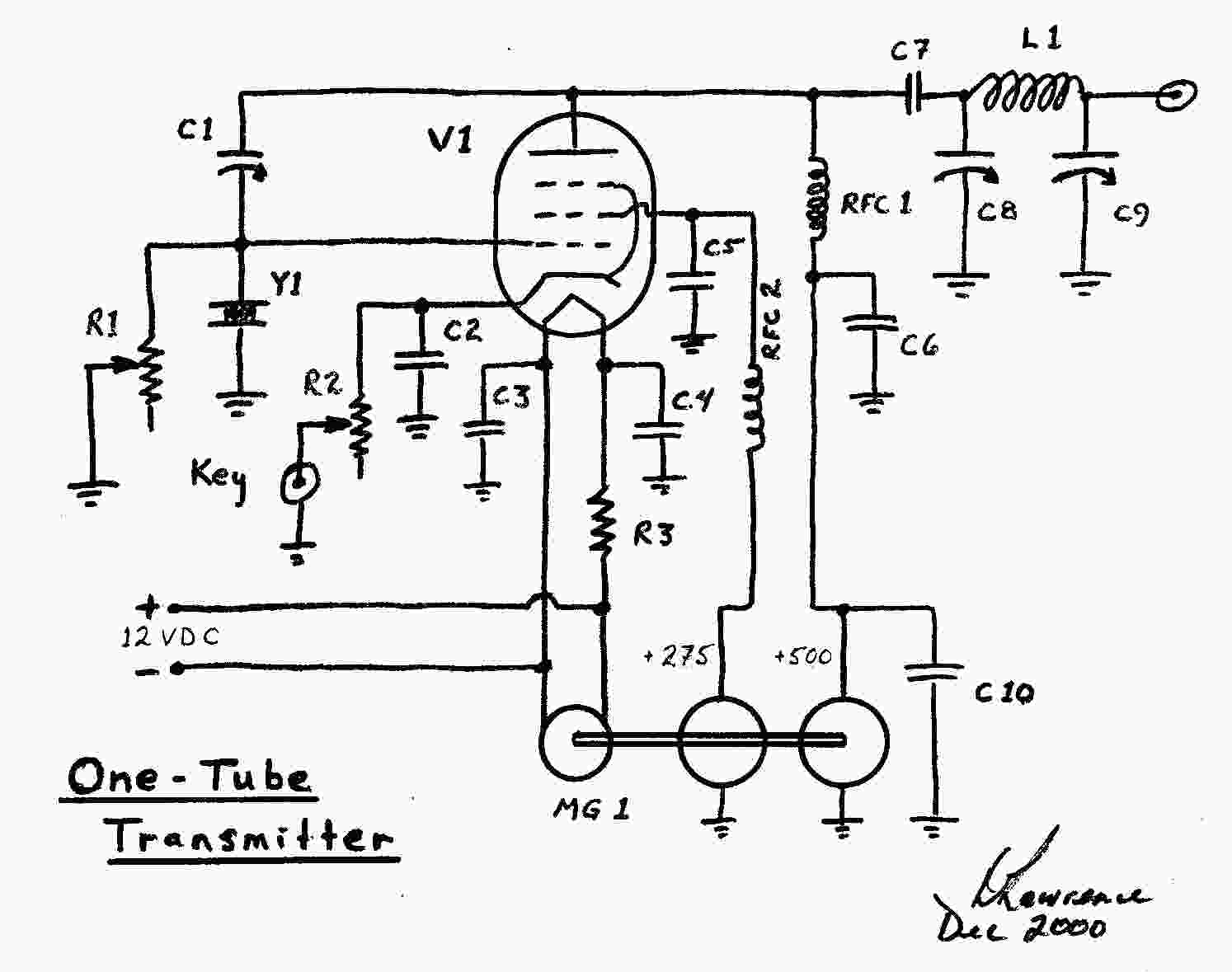
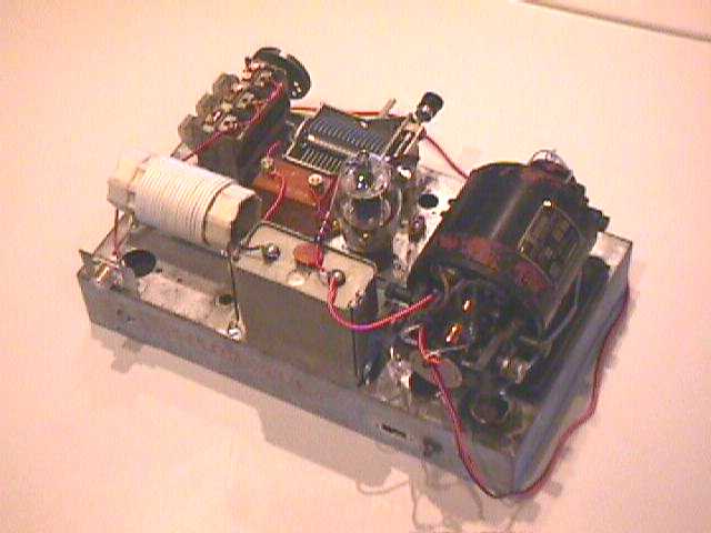