
One of the prides of my collection is a Wireless Set (Canadian) No. 19 with High Power Amplifier also known collectively as a Wireless Set No. 19 High Power.
It has taken many years to track down all the bits and pieces to assemble a complete system.
In the Public Archives of Canada, a letter was found that marks the introduction of the amplifier for the No. 19. On 3 June 1942, Canadian Military Headquarters (CMHQ) sent a letter to The Ministry of Supply stating that CMHQ had been advised that the Directorate of Signals Design at Ottawa were working on the development of a linear amplifier for use with the No. 19 set.
A brief description then followed with the following points:
1. Automatic linear class B amplifier with an "Expanding Circuit", i.e. the unmodulated drain is 15 amps at 12 volts; this drain increases with modulation to 40 amps at 100%.
2. The use of this amplifier does not involve any disturbance of the wiring or components of the 19 Set proper, except for one lead in the relay press-to-talk circuit and the aerial co-axial connection drive.
3. These modifications are both sufficiently simple to enable their being carried out in the field by means of adaptors.
4. A vibrator power supply has been designed to fit exactly in the standard case of the No. 19 Set with the amplifier utilizing an 813 tube located to the left of the power supply in a separate case. The whole combination is said to be mounted with convenience above any No. 19 Set.
The letter continued to say that this amplifier had been demonstrated successfully to the Canadian Marconi Company who were assembling twenty-five sets for life tests. They had concerns regarding the reliability of the vibrator at the required rating. It was then concluded that the output of this amplifier when compared on the same 16 foot antenna with a Canadian No. 9 Set showed about five times the power, i.e. approximately 100-watts.
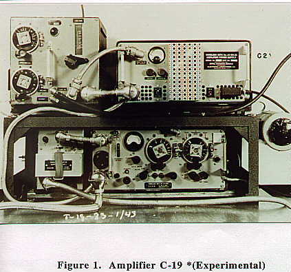
Figure 1 shows an early Amplifier C-19 *(Experimental) that was mounted above a No. 19 MK II. The Amplifier was at the top left and the Vibrator Power Unit was at the top right.
Working Instructions were published in May 1943 in the standard 5�" x 8" format with the brown wrinkle cover (36 pages and 5 figures).
The class of operation had been changed to an expanding linear class B/C amplifier with 100 watts output when fully modulated and 125 watts output on C.W. It was found that the voltage induced in the receiving antenna when transmitting with the amplifier, was enough to damage the Variometer. Therefore, a Variometer Protector Unit (V.P.U.) was introduced to open the connection between the antenna and Variometer.
This cylindrical unit was fitted to the back of the standard variometer. The current required to operate the internal relay was obtained from the Control Unit No 3A MK. II. The Amplifier appears to have been manufactured by The Royal Canadian Corps of Signals, and the Vibrator Power Unit Power Supply label reads "Wireless Sets No. 19 MK II Amplifier Power Supply, manufactured for Royal Canadian Signals, Contractor, Electronic Laboratories Inc, Indianapolis, Indiana".
Twenty five Experimental Amplifiers were received in the UK by the Canadian Army Overseas (CAO) for user trials in May 1943. The following information was found in the Public Archives of Canada:
Field tests were made and the sets, although more than meeting the range requirements, were found to radiate spurious (adjacent channel) and harmonic interference. The spurious radiation was present in the output of the WS No. 19 which the amplifier merely amplified but which, after amplification became a serious nuisance. The harmonic radiation was produced mostly by the amplifier itself and was a function of design. Consequent to the field trials, Canada was urged to rectify these troubles and, when this had been accomplished, the War Office would be asked to adopt the Canadian Amplifier. In the meantime it was decided that the CAO would equip itself with the British equivalent amplifiers.
Also from the field trials, the Chief Signal Officer of 2 Cdn Corps to Canadian Military Headquarters stated:
The Amplifier C19 was very well liked and is unquestionably very much the electrical superior of the British equivalent - the Amp RF No. 2. The reliable day and night range with 12' V aerial on freqs between 2.1 to 3 mcs was found to be approx 20 miles. The three major criticisms were: - i) High Harmonic radiation, ii) Electronic Vibrators failed frequently, iii) High battery drain.
Canada then produced a "Gremlin" box or filter unit for insertion between the WS No. 19 and the amplifier, designed to reduce spurious radiation. Two "Gremlin" boxes were tested in the UK and favourable reports were received. The first 25 experimental amplifiers were to be returned to Canada for salvage since they were occupying valuable space and were not considered suitable for field use.
In 1944, a new Amplifier Canadian No. 19 and Vibrator Power Unit, for use with the WS No. 19 and the WS No. 22, was introduced. This amplifier incorporated a very selective internal filter to suppress any spurious RF signals from the No. 19 set.
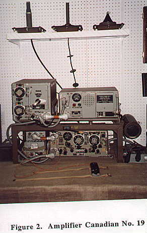
Figure 2 shows the Amplifier system in my collection. The Amplifier is at the top left, and the Vibrator Power Unit is at the top right.
The Amplifier was made by Rogers Majestic and the Vibrator Power Unit was made by Electronic Laboratories of Canada Ltd. It was very similar in appearance to the Amplifier C- 19 *(Experimental) with slight differences in the layout of the front panels. The class of operation remained the same, i.e. expanding, linear, class B/C.
The weights of the units are quite notable. The Amplifier weighs 47 lbs, the Vibrator Power Unit weighs 77 lbs, the mounting frame and leads weighs 48 lbs, for a total installation weight of 172 lbs! If this is then added to the standard No. 19 Set weight of 88 lbs, the weight of the equipment totals 260 lbs. A good starting point of assembly is a very sturdy table!
It is interesting to note that the WS Cdn No. 52, that was introduced in the spring of 1944, uses virtually the same output circuit as the Amplifier. I tend to think of the WS 52 as a repackaged WS No. 19 High Power. The No. 52 weighs 245 lbs! Many accessories were supplied with the amplifier system but two stand out as very specific to this system as follows.
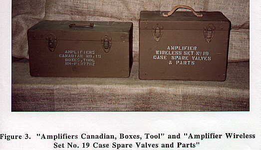
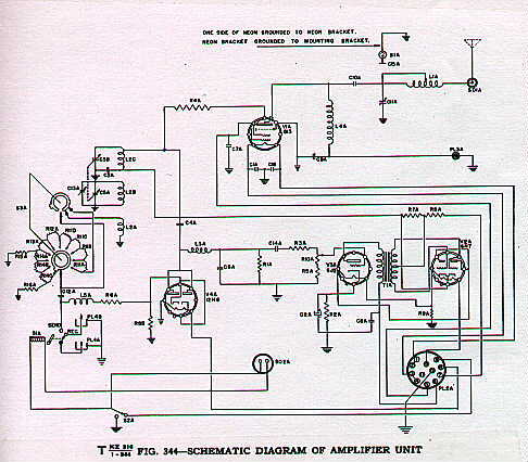
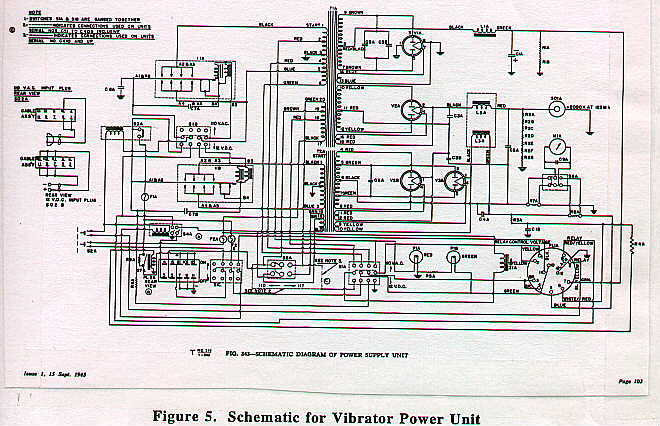
Two wooden boxes with metal handles known as "Amplifiers Canadian Boxes, Tool" and "Amplifier Wireless Set No 19 Case Spare Valves and Parts" are shown in Figure 3. The schematic for the Amplifier is shown in Figure 4. The schematic for the Vibrator Power Unit is shown in Figure 5. I have found that the specifications for the output power of the Amplifier are very conservative:
Approximately 60 Watts on R/T fully modulated and approximately 75 Watts on CW.
I have been able to achieve 215 Watts output on 80 metre CW and 127 Watts output on 40 metre CW.
The original order for the amplifier system was for a quantity of 500 units. The highest serial numbers that I have seen are Amplifier Serial No. C452 (produced Feb 8, 1945) and Vibrator Power Unit Serial No. C485.
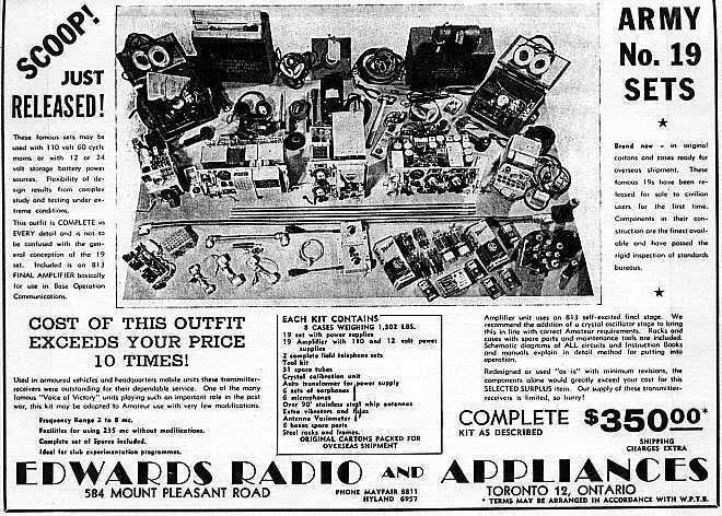
Many instructional documents for the Amplifier Canadian No. 19 are dated as late as October 1946. An interesting advertisement that appeared in XTAL Magazine May 1946, published by The Canadian Amateur Radio Operators' Association, Toronto, Ontario is shown in Figure 6.
The No. 19 complete with high power amplifier and all accessories was available for $350 Canadian on the surplus market.
This was roughly equivalent to two months of average wage in 1946 or $5,000 Canadian dollars in 1995. Note the shipping weight of 1,302 lbs, shipping charges extra! Interestingly, the WS No. 19 and Amplifier system was again used in action in the Korean War.
Not many Wireless Set No. 19 High Power are known to exist today, and I am glad to share this information with fellow collectors. I welcome any additional information and anecdotes from readers to further complete the picture.
Photos by Deborah Bisaillion
Figure 1. Amplifier C-19 *(Experimental) Figure 2. Amplifier Canadian No. 19 Figure 3. "Amplifiers Canadian, Boxes, Tool" and "Amplifier Wireless Set No. 19 Case Spare Valves and Parts" Figure 4. Schematic for Amplifier Figure 5. Schematic for Vibrator Power Unit Figure 6. Advertisement for Wireless Set No. 19 Equipment from XTAL Magazine, May 1946
Copyright by Chris Bisaillion, VE3CBK. Photos copyright Deborah Bisaillion. All Rights Reserved. Nothing on this page (or associated photograph pages) may be copied or distributed without written permission of the author and/or photographer. In addition, credit must be given to those media in which the article has appeared, including The Original Wireless Set No. 19 Group website.
Thanks for honouring this request.