BACK TO HOME PAGE
INDEX
The Montreal
525 Fox V1.2 fully compatible with
International Hunts in zone 2 (ARDF).
WARNING :
THIS PORJECT IS ONLY FOR
THE BRAVES WITH A SOLDERING IRON
Hardware by Jacques VE2EMM.
Software by Francois VE2JX and Jacques VE2EMM.
Special thanks to Joe Leggio WB2HOL and Doug Reed N0NAS.
This project is free for non commercial use by Ham radio
operators only.
FEATURES
-
8 selectable ID codes, "MO", "MOE", "MOI", "MOS", "MOH", "MO5", "MON",
"MOD".
-
For 1 minute, it continuously sends the selected ID code at 8 WPM and terminates
by a fast "DE hider's call
letters".
-
Cycle times are: continuous to 7 minutes, depending on the numbers of FOXES
in the hunt. 5 FOXES and 5
minutes is the international standard. More or less FOXES can be used
for practice.
-
Delayed start up to 3 1/2 hour, in 1/2 hour increment, all FOXES can be
synchronized by a single PB.
-
MCW.
-
The Hider's call letters can be loaded in the EEDATA memory permanantly
and changed just by setting switches.
-
The indicating LED shows 1- Delayed start timing, 2- Incorrect combination
of time and # of FOXES, 3- CW
keying being done.
-
Small size, 2.5" X 2.75".
-
Power consumption is 12 mA while timing and 180 mA while transmitting from
12 Volts.
-
Power output on 2 Meters is at least 0.8 Watt, it can be increased to over
1 watt.
-
FM modulation.
-
Uses any fundamental Xtal above 5 mHz.
-
Output frequency; any 2 meters frequency. (Use
the ICS525 caculator of the Web to select which legs to ground)
-
Has only a few semiconductors, an ICS525 OSCaR User
Configurable Clock, 1 transistor, a PIC controller and a 78M05 voltage
regulator.
The PCB dimensions are 2.75 X 2.5 inches
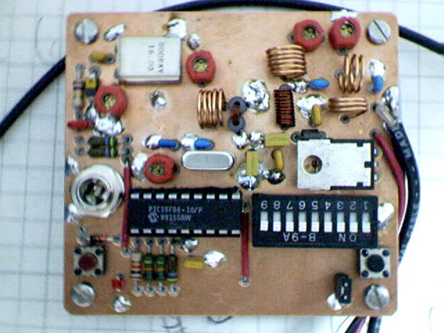
Montreal 525 Fox TOP VIEW
WARNING
-
The ICS525 is a surface mount IC. It is a 28 pins
narrow SSOP package, that is; 28 pins in a box of .4" X .15".
The Legs spacing is .025" center to center.
Can you solder it? With a good hand, it can be
done. It has been done 8 times.
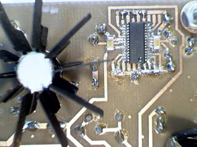
Montreal 525 Fox Part of the BOTTOM VIEW
SOLDERING SURFACE MOUNT DEVICES
Using a very small soldering iron tip, put a small quantity of solder on
a corner pad.
Position the device carefully with pair of tweezers.
Solder that corner pin while maintaining the alignment of the device on
all the pads.
Solder the rest of the pins with a very small amount of solder.
INFORMATION
Features and operation text.
Give your Xtal
frequency and your operating frequency to ICS, they you will tell you
which pins have to be grounded on the ICS525.
Construction text.
Parts list V 1.2
Get information on the availlability of the ICS525 from ICS.
I purchased mine from Electro Sonic
Inc. in Toronto Can. (Shop as a guest, search for "ICS525-01R")
Info from Phil Barnes-Roberts AD6PQ: "I got the ICS parts from
http://www.nuhorizons.com/ "
Use a PIC16F628 for all new construction, it cost less and is a better
performer.
Fine print:
All material on this page is distributed on a
WYSIWYG basis and as such I can't take any responsibility for the use of
this design and its results. However in saying this it must also be mentioned
that every effort has been taken to ensure that it as error free
as possible.
BACK TO HOME PAGE INDEX
Many thanks to Al Waller K3TKJ for graciously hosting my web pages
on QSL.NET.