Last update, March 23, 06
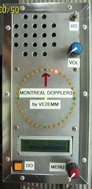
FRONT PANEL
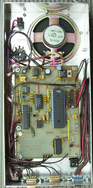
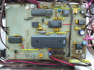
INSIDE
VIEW
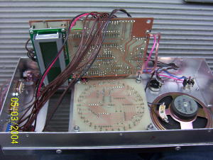
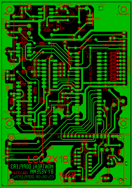
2 BOARDS ARE BACK TO BACK
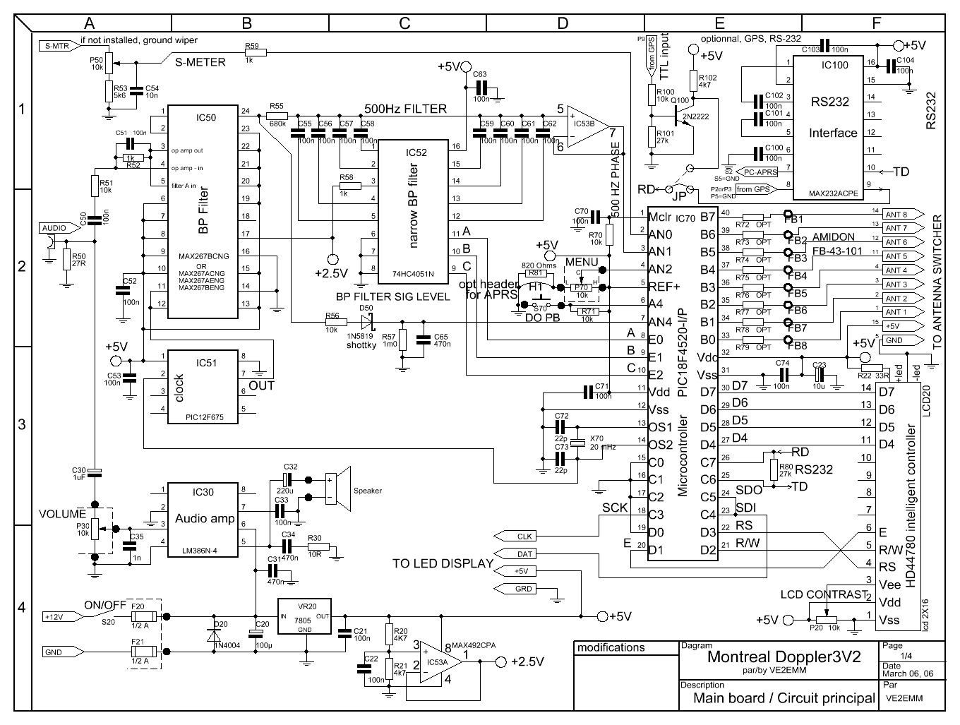
MAIN BOARD
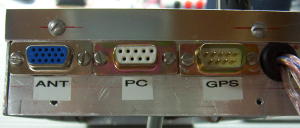
CONNECTORS
Lots more pictures on the web page of the AMATEUR RADIO CLUB VE2UMS:
http://www.ve2ums.ca/chasse/Serge/Transmitter%20Hunting/Doppler/doppler_links.htm
Please contact me for more info.
FEATURES
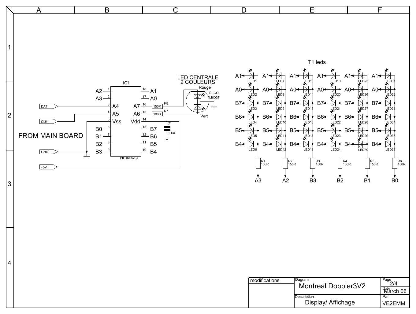
- 36 LEDs display; center LED when green = good signal, when
red = no signal , the direction is frozen to the last good signal.
- Uses 3 PICs; a PIC16F628A for the display, a PIC18F4520 as
the main processor and a PIC12F675 as a frequency divider.
- Filters; a Max 267, the best bandpass filter that I have ever
seen, followed by the Roanoke switch cap filter for very narrow band
width (+/- 0.5Hz).
- My DopplerII integrating and phase detection software in the
main PIC.
- LM386 for monitoring the audio independently from the
doppler.
- Simpler menu selection, turning a selection pot and a pushing
a DO switch.
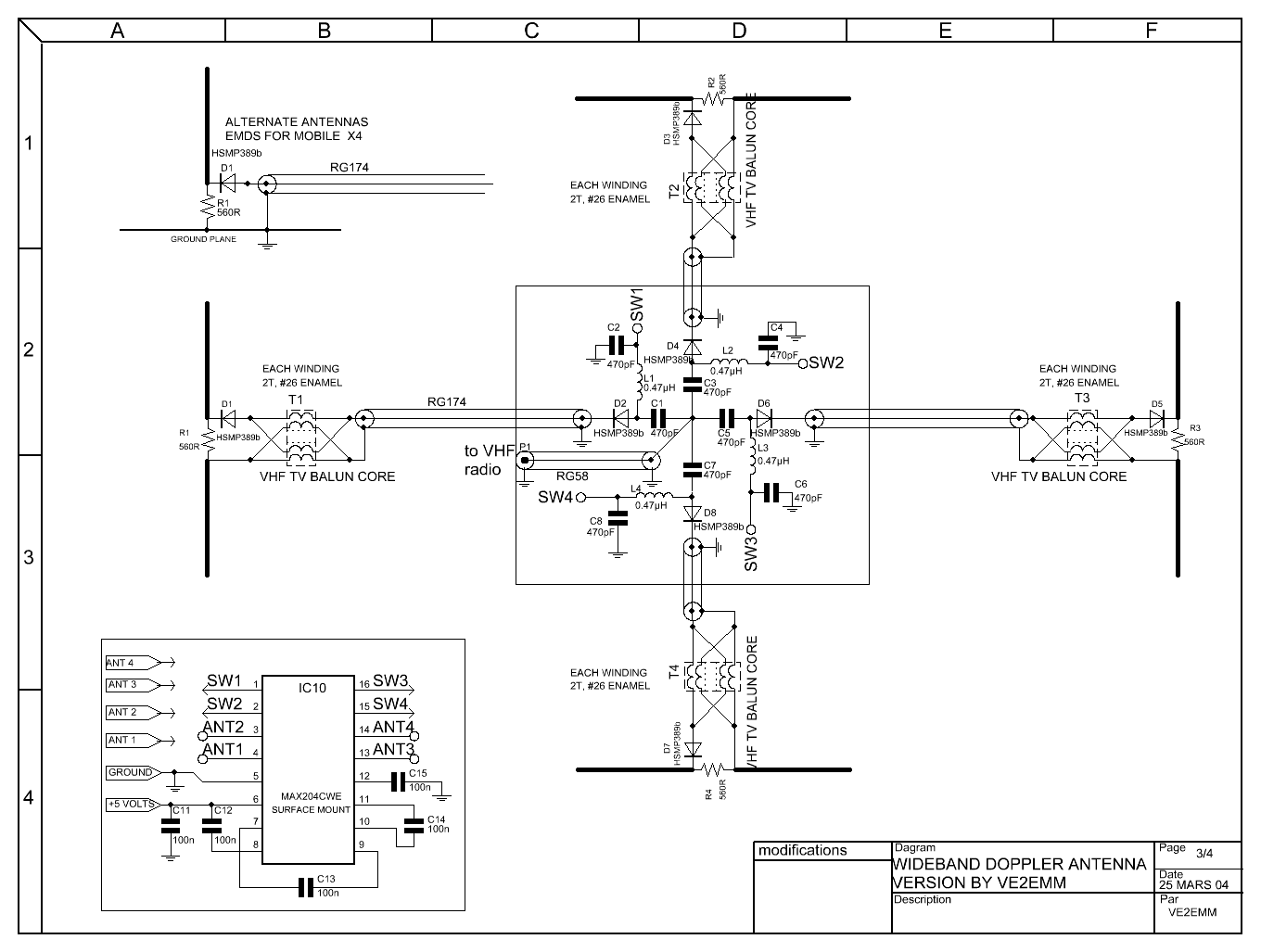
- It will switch 4 antennas with a + or - going signal, 4
antennas differential, 8 antennas with a + or - going signal.
- Pushing the DO PB sends the direction to APRS. The
protocol is: <cr><lf>%359/Q<cr><lf>. The
Q (0<8) is the
quality of the signal just before the
extraction of the phase information.
- GPS information goes through the doppler, it will be instantly
interrupted when the doppler sends a DF to APRS on a PC.
- Faster main processor, PIC18F4520. **** NEW **** June 06
THE MENUS:
0 - Main operating position ;
First line shows: Quality Factor(signal out
of the last soft filter in the PIC), direction in deg., # of returns
being integrated.
Second line shows: A bargraph of the
signal level out of the MAX267 input filter or
a S-Meter DC signal from your radio if needed.
The DO Push Button alternate between
no signal processing and selected integration.
This menu can be removed by removing
a jumper (H1) if only APRS is in use.
1 - Also a main operating position;
First line shows: Quality Factor(signal out
of the last soft filter in the PIC), direction in deg., # of returns
being integrated.
Second line shows: A bargraph of the
signal level out of the MAX267 input filter or
a S-Meter DC signal from your radio if needed.
The DO PushButton sends a DF to a PC.
(via RS232)
2 - Reduce the quantity of integration by pushing the DO
PB.
3 - Increase the quantity of integration by pushing the DO PB.
4 - Auto calibration to foward by pushing the DO PB.
5 - Reduce the calibration position manually by pushing the DO PB.
6 - Increase the calibration position manually by pushing the DO
PB.
7 - Selection of the minimum Quality Factor (1<8) for
displaying a good return. Less then the selected number, freeze
the display to the last good return.
8 - LCD display, BRIGHT / DIM control. **** NEW **** June 06
9 - Future menu
10- Selection of the DF to PC baud rate, 2400, 4800, 9600, 19200.
11- Bargraph selection of the S-Meter from a radio or the level out of
first MAX 267 filter.
12- Selection of 3 complete setup for different radios or cars. **** NEW **** June 06
13- Selection of antenna rotation CW or CCW.
14- Selection of antenna switching, 4 +/- and 4 differential or 8
+/-.
15- Selection of antenna under test. (individual activation of each
antenna)
Main board schematic with scope waveforms for trouble shooting
Parts list Doppler3V2.
Parts list Doppler3.
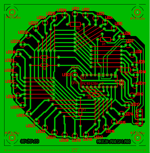
Display board
Main board
May I suggest the use of Joe Moell K0OV's wide band antenna
system
for this doppler. It is on the Homing
In web site.
| Here is the viewer/printer
software for the schematic, and the complete schematics
for the doppler3V2, includes the switcher. Here is the viewer/printer software for the PCBs, and the complete PCBs files for the doppler3V2, includes the switcher. The above viewers are self contained software and do not leave traces in your PC. Buy the PCBs and PICs from Fred KF9GX at Far Circuits. I can program your PICs, the source program and the object code is also availlable for Amateur Radio use only by writing to VE2EMM. |
SUGGESTIONS
Please send your suggestions
and requests, they will be appreciated.
Thanks & 73, Jacques VE2EMM
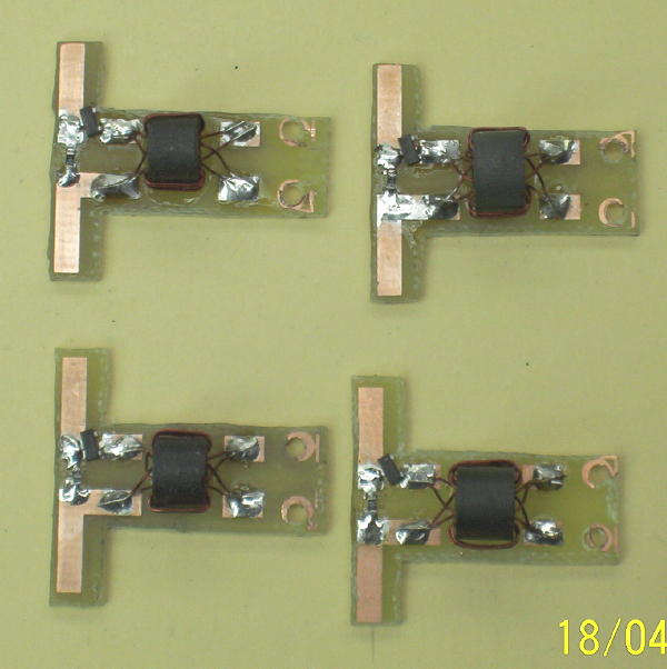
My new untested
switcher, a variant
of
Joe Moell wideband switcher. One more untested antenna switcher
prototype.
Switcher center, switcher antenna ends