
The Homebrew Microwave Transverters
The 1st, and 3rd stage pre-amplifiers are modified KU band LNA's, the 2nd stage is a Down East Microwave kit. The oscillator source is a California brick with a temperature controlled oven. The mixer stage was also built from a Down East Microwave kit. The final output stage is capable of ~50 mw but is attenuated to a 3 mw level in order to safely drive a 100W I/P TWA for ~10W O/P. The input frequency of the homebrew transverter is 435.5 MHz with attenuators installed between PA I/P and transverter. The transceiver has attenuators in the O/P to reduce the drive from 25 watts to a few milliwatts. A simple 435 MHz pre-amplifier is used to overcome the loss of the attenuators. A diode switching circuit is used for TR switching on the I/P side. A Transco SMA relay is used to switch between transmit and receive in the transverter. The I/P to the first stage pre-amp is a waveguide, (centre top view below) and is connected to a large rotatable waveguide RF switch located on the front panel of the 100W amplifier, this allows switching between transmit and receive. A three port circulator is located between the O/P of the TW tube, it's O/P connects to the waveguide RF switch. A directional coupler, (bottom picture) connects to the O/P waveguide shown near the middle of the picture. The directional coupler is used to monitor both the forward and reverse power.
10GHz
transverter
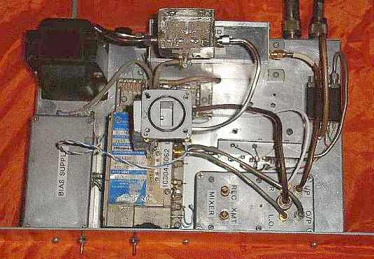
Front top view
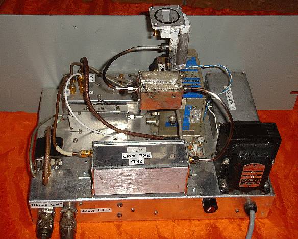
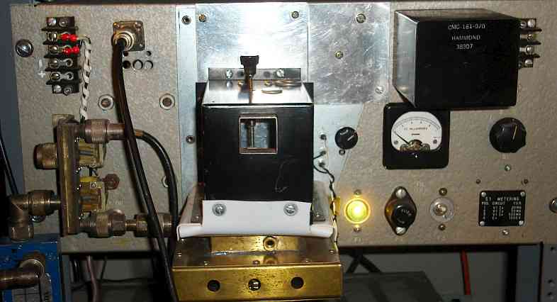
Back view
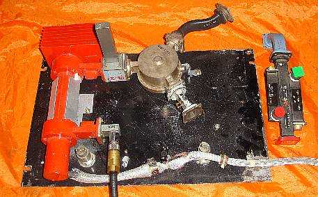
100W I/P ~10W O/P 10GHz TWT Amplifier
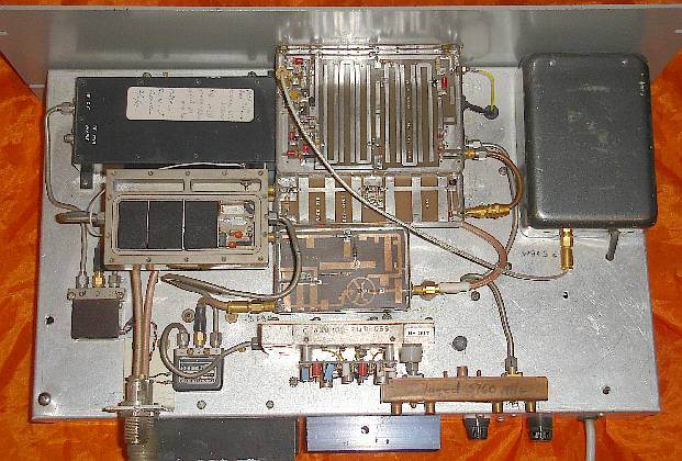
The 5.7GHz transverter top view
The 5.7GHz transverter bottom view
Homebrew 2m 1KW Linear Amplifier
Top view home brew 2m linear amplifier
Front top view
Back view
100W I/P ~10W O/P 10GHz TWT Amplifier
The 5.7GHz transverter top view
The
1st and 2nd stage pre-amplifiers are modified C-Band
LNA's. The mixer, oscillator and filter circuit boards
(centre) were built from
Down East
Microwavekits.The
crystal oscillator source for the mixer is in a temperature
controlled oven and mounted in a separate enclosure (grey box
on right side). The output PA(upper left black box) was a
commercial linear brick capable of 10 watts O/P. The 2nd
mixer stage,
(not shown) runs at a frequency of 1296 MHz, the driver for that stage
is a Yaesu FT-480R transceiver running on 144.0 MHz.
A couple of Transco SMA relays are used for switching between
the I/P and O/P stages on xmt and rec.
The 5.7GHz transverter bottom view
Homebrew 2m 1KW Linear Amplifier
Top view home brew 2m linear amplifier
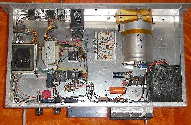
The
2M amplifier uses a
pair of Eimac ceramic 4CX250B's. All of the plate tuned tank circuit is
made from copper sheeting then silver plated using a product called
Cool-Amp. The chimneys are not shown in the picture. The metering
circuit is capable of measuring grid current, screen current, bias
current and plate current. As well, it can measure screen voltage, bias
voltage and plate voltage. An RF output detector is also incorporated
in the metering circuit to aid in tuning. The tubes are forced air
cooled with ~100 CFM. The amplifier can be driven with as little as 8
watts in linear mode. The homebrew power supply can deliver 1850V at
600 mA for 1KW I/P. The transformer originally only put out ~1000 VAC
but we were able to get more power for our buck, by using a simple
boost circuit consisting of a couple of smaller high current
transformers. The booster circuit also allows us the ability to go from
low to hi power at a flick of a switch.
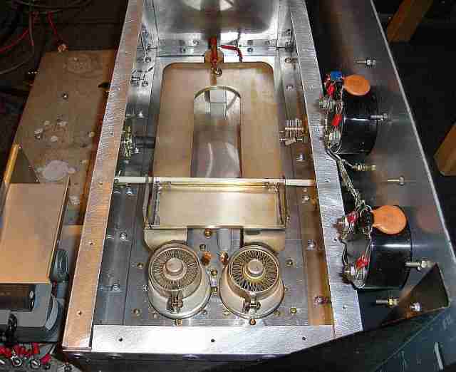
Top view of tubes
O/P tank design
Top view of tubes
O/P tank design
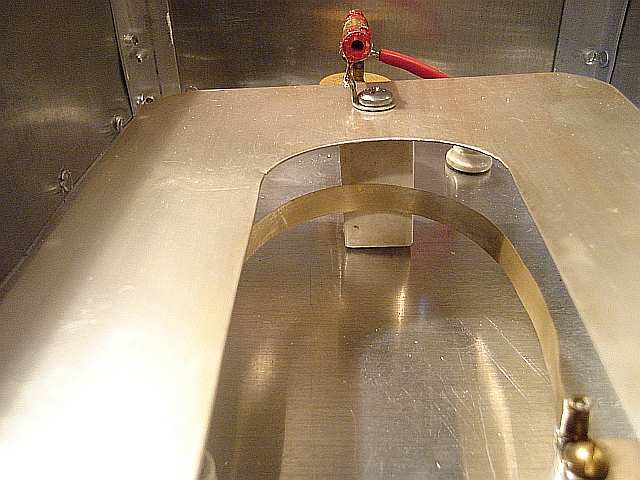
The
output is tuned by
using a capacity coupled vane which comes in close proximity to the
output tank circuit, adjusted from the front panel. A PTFE rod with
adjustable screw stops the output tunning vane from coming too close to
the tank line and causing a short.
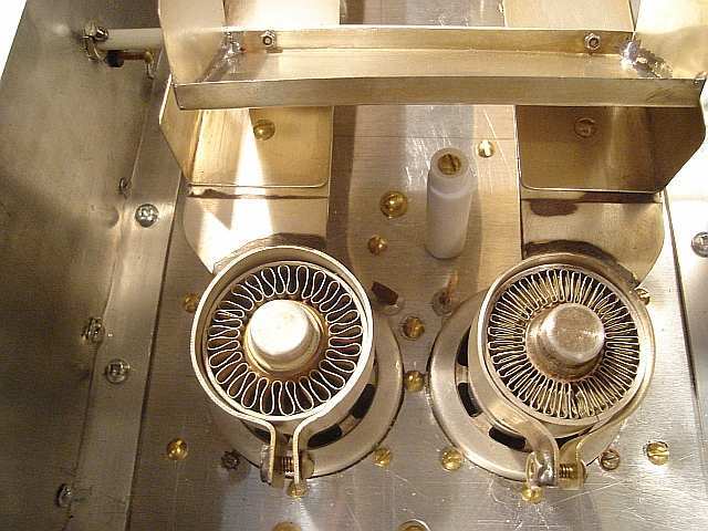
View of loop
View of loop
Closeup
of output coupling
loop under tank circuit. The output coupling consists of a copper strap
located under the plate tank and is tuned by a small variable capacitor
located on the front panel.
Grid compartment
Grid compartment
Neutralization
is
accomplished by means of a pair of small gauge wires which cross over
from one tube to the other on the underside, then through the chassis
to the top side. On the top side each of the leads from the grid has an
adjustable copper tab that can be moved closer or further from the side
of the tube.
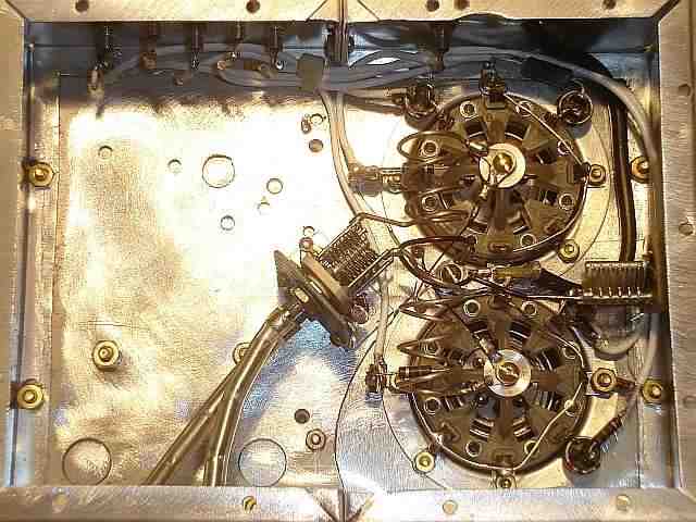
Homebrew
1296 MHZ Transverter
The
1296 MHZ transverter
consists of a SHF 1240K, 1240-1300 MHZ linear transmit/receive
converter kit. The input frequency is 144.0 MHZ with only +10-13 dbm
drive. Small RF relays are used to switch the I/P and O/P stages. The
output stage uses a Mitsubushi RF power module M57762 with an O/P of
~18 watts nominal. That module is driven by an NEC SC1043 RF power
module which is running at ~2 watts. The 1st stage pre-amp consists of
a MGF1402 GAS FET followed by a 2nd stage Miteq AFS42 low noise amp.
The +12V power supply is mounted separate from the rack unit.
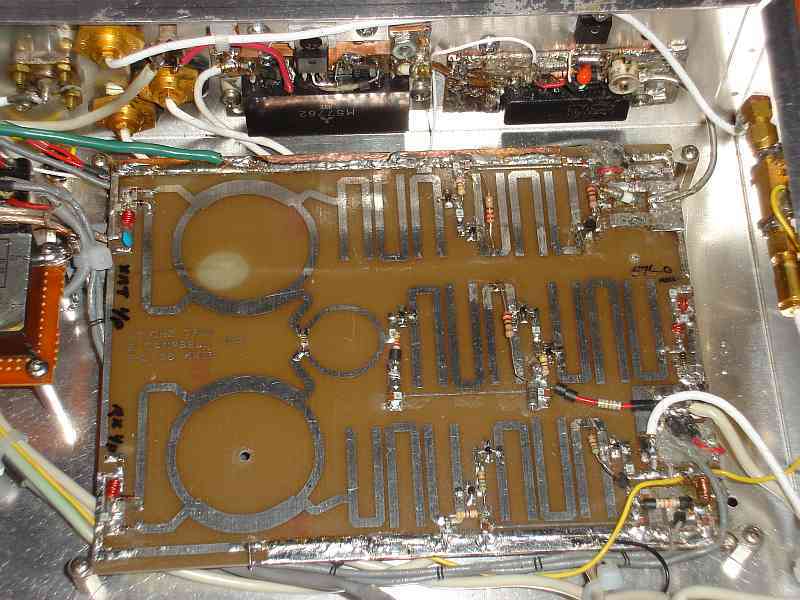
View of mixer (centre) using stripline layout
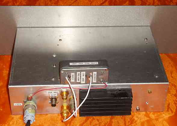
Back view of transverter with heat sink visible and 1st stage pre-amplifier
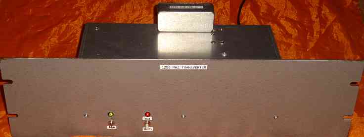
Front view of transverter
Power Amplifier
The transverter drives a couple of forced air cooled 3CX100A5 triodes in grounded-grid (schematic) with ~1200V on the plates.

View of mixer (centre) using stripline layout
Back view of transverter with heat sink visible and 1st stage pre-amplifier
Front view of transverter
Power Amplifier
The transverter drives a couple of forced air cooled 3CX100A5 triodes in grounded-grid (schematic) with ~1200V on the plates.
Front view of 1296 100W
grounded-grid amp. (Mechanical
dwg)