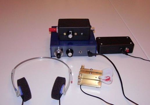
A Portable Station for 30 Metres
Last time I went camping with my son, I thought that it might be nice to have a small rig that I could take hiking and on business trips.
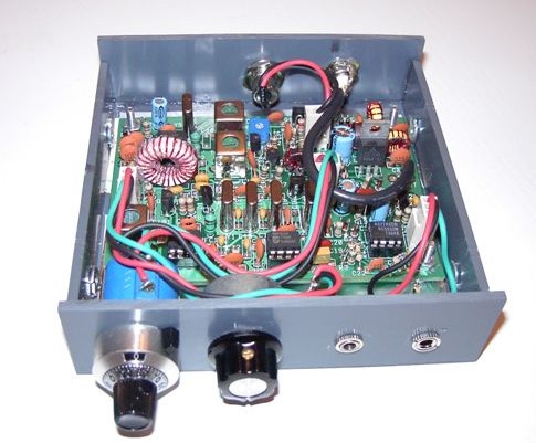
Looking through the QRP-L archives, there were a number of recommendations for the Small Wonders Labs SW+ series designed by Dave Benson. At $55 USD postpaid, the SW30+ is a super value for a superhet transceiver. I decided on the 30 metre kit, because 30m has less static in the summer months than 40m, but would also support evening operation from a hotel room, even during sunspot minimums.
I had previously ordered a bag of T-68-7 cores from Dieter W8DIZ, so I substituted one of these bigger cores for the T-50-6 core that was provided with the SW30 kit for the VFO. I reckon the T-68-7 core should have slightly better temperature stability and a bit more 'Q', as well. I built my own cabinet using 1/8" PVC.
Originally, I had planned on putting a keyer inside the transceiver case, but in the end decided to house the keyer separately, so I could use it for code practice. The Norcal keyer is a nice little kit. I power mine with a 9 volt battery. The ScQRPion paddles (#192) were purchased unbuilt from a QRP-L list member.
Then, what to do for an antenna? An inverted V would have been fine for hiking, but what about operations from a hotel room? I decided that the end-fed half-wave antenna (EFHWA) would do the trick, but then I had to build a tuner.
I made a few NEC-2 models of various configurations of the EFWHA and saw that the impedance would vary depending if it was operated as a vertical, sloper, inverted L, or horizontal dipole. In a vertical or sloping configuration, NEC-2 seemed to indicate an impedance of approximately 3.4k ohms with #22 wire, while an inverted-L would have an impedance of roughly 4.9k ohms
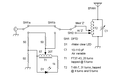
An L-match would have been ideal, but I was looking for small and simple. In the end, I compromised on a parallel-tuned circuit, but I used a DPST switch to select between two taps to arrive at the appropriate impedance transformation. I used 31 turns on a T-68-7 core, in parallel with a 110 pf air variable capacitor. I believe the unloaded Q for this inductor *should* be at least 200 at 10 MHz.
With 31 turns on the T-68-7 core, I added taps at turns 3 and 4 to provide an appropriate match for 5k and 3k loads, respectively. Testing with resistive loads of 3k and 5k, I found the tap on #3 turn provided a higher impedance transformation than calculated, with the tap on #4 turn being just right for 5k, so I ended up with a tap on #4 turn to match 5k loads, and a tap on #5 turn for 3k loads.
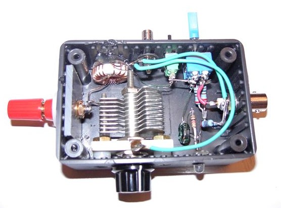
I used a resistive bridge circuit for tuning, with a FT37-43 ferrite toroid autotransformer driving a water-clear LED, as suggested by N7VE. This cct can detect high SWR with just 10 mW from the SW30. The bridge LED is very bright when any mismatch is present, when running the SW30+ at 2 watts.
After having built the parallel-tuned matching circuit, I found an interesting article on W8JI's website on this subject which caused me to wonder what were the losses associated with this circuit. I decided to build a second parallel-tuned matching circuit and connect the two back-to-back.

First, I measured the peak voltage of the SW30 into a 52 ohm dummy load. After removing the dummy load, I tuned the first parallel-tuned circuit for minimum SWR with a 5k load across it's output. Then, I connect the second parallel-tuned circuit across the first, with the low impedance side connected connected to the 52 ohm dummy load, tuned the second parallel-tuned circuit for minimum SWR, and then measured the voltage across the dummy load. The voltage ratio was 13.45/14.2, which corresponds to a 0.47 dB loss. Assuming losses are even distributed between the two parallel-tuned circuits, the loss for one parallel-tuned circuit should be ~0.25 dB. This figure agrees with G4FGQ's 'TUNEHALF.EXE' application.