6/11/08
A 12 element long yagi for WWNY Channel 7
A few posters on digitalhome.ca had expressed interest in receiving WWNY when that station starts to broadcast HDTV on channel 7 in 2009. I thought it would be interesting to scale an amateur 2 metre long yagi design to that frequency.
I picked
VE7BQHs BQH12J 12 element yagi, given its good gain, pattern and excellent bandwidth. Many current long-yagi
designs are peaked for performance on a relatively narrow band of frequencies, not so with the BHQ12J.
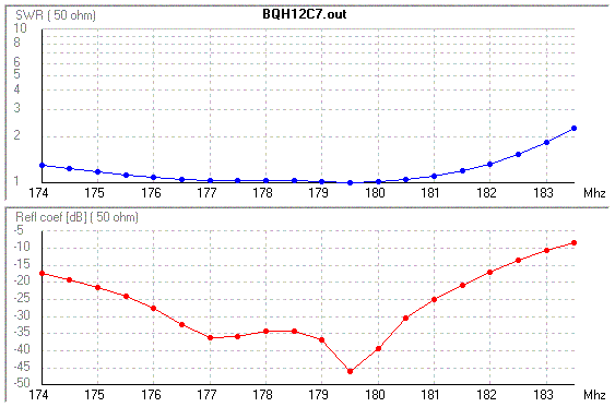
This is important given HDTVs 6 MHz-wide occupied bandwidth, especially when factoring
in water accumulating on the elements during rain showers.

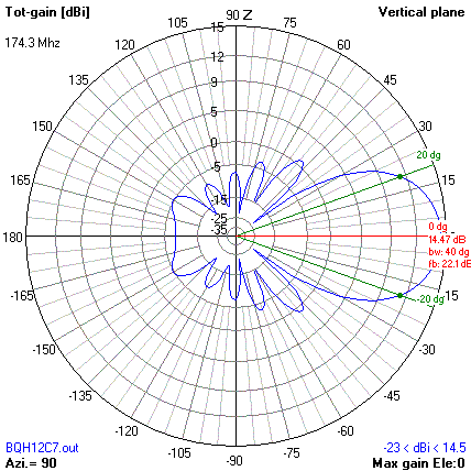
As you can see from
the 4NEC2 gain graph, gain (expressed in dBi) is fairly constant across the channel of interest.
Performance is purposely peaked at the high frequency end of the channel, as the accumulation of water droplets
will cause the peak gain to shift downwards by up to 3 MHz.
As this is an amateur radio design, the driven element impedance is intended to be a nominal 50 ohms. I would suggest a split-dipole feed for ease of construction. If a pre-amp (highly recommended) with a 70 ohm input impedance is used, a quarter wave matching section of 50 ohms will transform the input impedance closer to the desired 70 ohms. Just remember to account for the velocity factor of the coax when cutting your matching section.

The NEC input file is here.
Construction Details
|
Element |
Element position (mm) |
Element length (mm) |
Diameter (mm) |
|
Reflector |
0 |
832.3151 |
4.76 |
|
Driven element (DE) |
291.7241 |
801.5221 |
8.00 |
|
Director 1 |
425.4310 |
764.2461 |
4.76 |
|
Director 2 |
729.3103 |
759.3841 |
4.76 |
|
Director 3 |
1093.966 |
742.3669 |
4.76 |
|
Director 4 |
1519.397 |
736.6943 |
4.76 |
|
Director 6 |
1993.448 |
732.6427 |
4.76 |
|
Director 6 |
2503.965 |
725.3497 |
4.76 |
|
Director 7 |
3038.793 |
722.1081 |
4.76 |
|
Director 8 |
3597.931 |
721.2979 |
4.76 |
|
Director 9 |
4225.948 |
718.0565 |
4.76 |
|
Director 10 |
4720.258 |
714.0047 |
4.76 |
With the exception of the driven element, this design calls for a 1" metallic boom, with all the elements, except for the driven element, mounted through the boom and insulated. Be forwarned that should if you change the diameter of the elements or the boom, you are changing the design and thus the performance. If you change to a non-metallic boom, remove 4.14274 mm from the length of each element. A metallic boom, even with insulated elements, has a shortening effect on the elements. Removing 4.14274 mm will return the design to its "free space" value as shown in the NEC2 model. Accuracy to the nearest millimetre is sufficient.
An inexpensive method of achieving insulated through-boom mounting is to cut a 2" section of heatshrink tubing over the middle of the element and use a heat source to shrink it tight. Drill the hole in the boom so the element, with heatshrink insulation, fits snugly through the boom. Use a hot glue gun to fix the element in place.
Plexiglass and hobbystore brass tubing can be used for the driven element. Brass tubing will allow you to solder directly to the driven element and, if you buy the next smaller size of tubing, will allow you to make adjustments to the length of the DE. I have an MFJ meter that covers the lower portion of channel 7, and would be happy to help come out and tune the antenna.