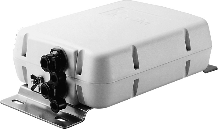
I have used AH4 tuners with my Icom rigs for many years.
Also for many years I have hated dealing with the installation of them for fixed or portable operation, so I finally broke down and benched the tuner and started making it more friendly towards to use.
What I didn't like:
1) No connector on control line; To connect / disconnect the contol lines one has to open the case, juggle 8 small screws and a gasket that doesn't like to stay in place. Futz with the terminals and then reverse the process. Otherwise for /P coil up the control line while still attached and carry the mess around.
2) Short factory pigtail; Using the factory coax would require use of a SO-239 female-female to mate with another PL259 for the run to the shack. No easy direct RF connection / disconnection. If I attached my own coax then the lid stays with it. Not handy for /P operations or even fixed operations for that matter if the tuner needed to be removed for any reason.
My goal was to get rid of these two problems and make a unit that could easily be disconnected and moved with minimum effort. It would also make packing the AH4 a breeze.
|
|
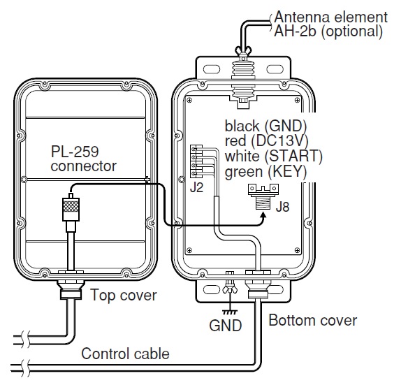
The way Icom says to use the AH4 |
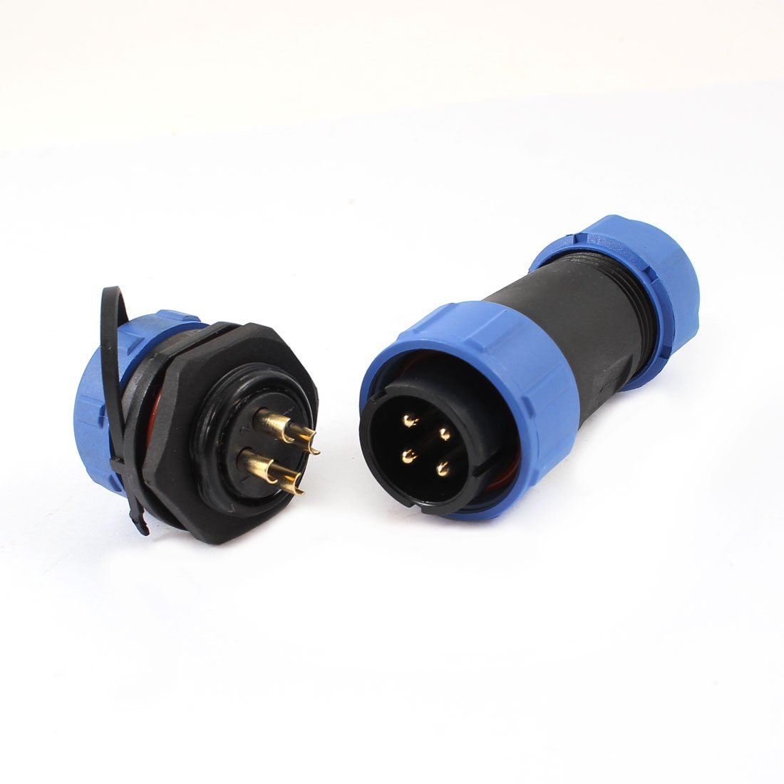
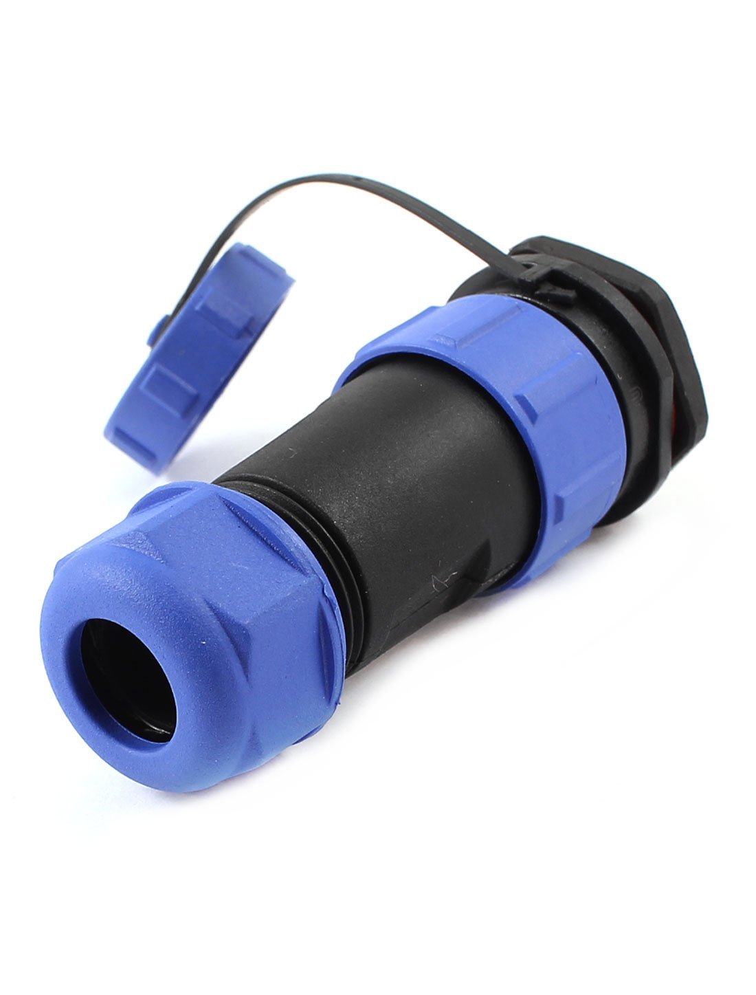
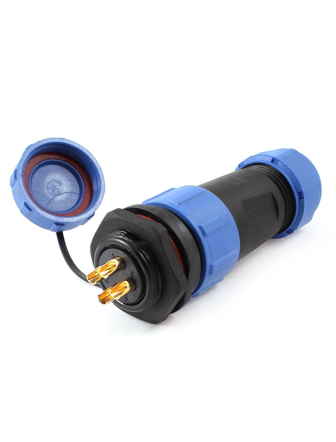
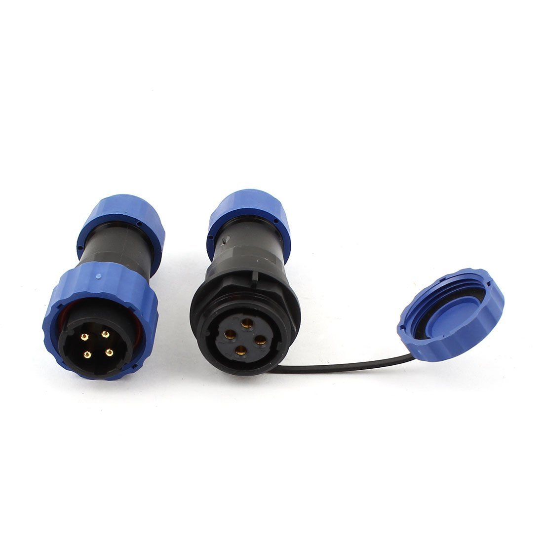
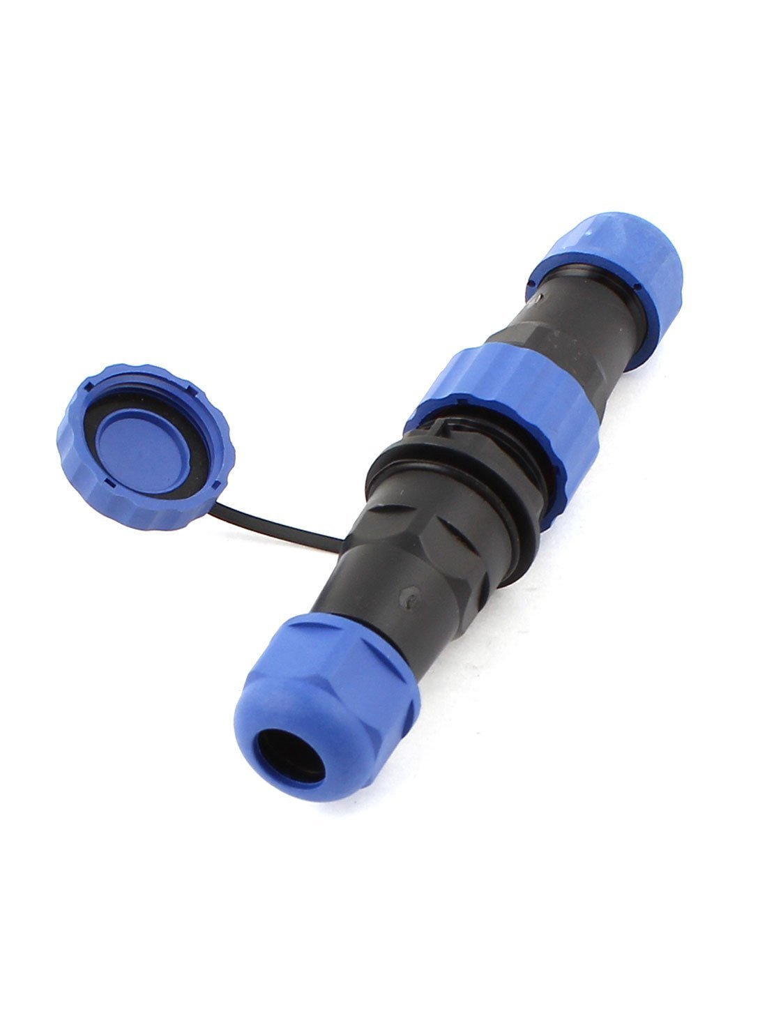
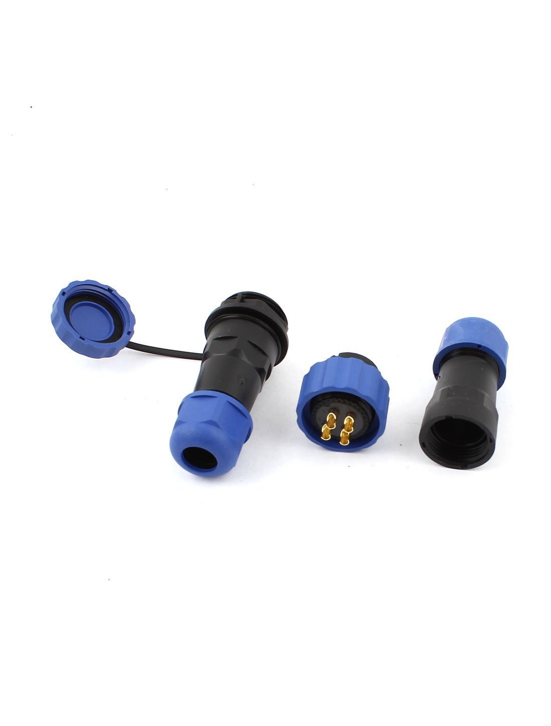
I found some waterproof connector on Amazon for a few bucks and bought a set with a panel jack and a hooded plug. I also bought a set that has hoods on both the male and female. I used the set with the panel mounted female for my tuner.
I have no idea what these are used in avition for as I've ever seen them on anything I've flown or worked on. At any rate they are a nice connector for the money and will suit my needs perfectly.
First ...The old control line was removed and the old cable grip removed. The new panel mount is just slightly larger than the one Icom cut so I used a round file to open the hole just a little. Also, the nut will not fit the housing unless you remove the stop which Icom used to hold their nut in place for tightening. For this I used a Dremel tool with a small grinder bit and ground it off.
Solder the control lines to it before installing permanently as it is much easier to do while outside of the housing than when it is in place. I used Icom's sequence from top to bottom of their connector and soldered them to the connector as follows: BK-1, RD-2, WT-3, GN-4. After these were soldered I cut the cable to length and terminated the opposite end to the Icom connector.
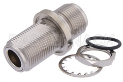
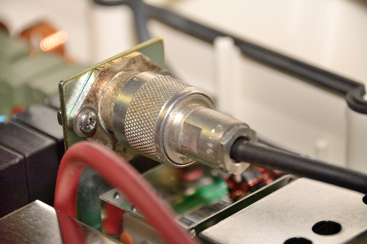
Next was to replace the short section of coax and cable grip. Once you loosen the nut on the grip the whole assembly can be removed without the need to remove the connectors. In the now open hole I unstalled a bulkhead Type N female to Type N female.
The short side is the external side and the longer side with the nut goes to the inside of the housing. The factory hole is larger than it needs to be, so center the connector the best you can and tighten. You may omit the gasket as it does not make contact due to the oversized hole. This will be sealed with clear RTV once everything is assembled ...so no worries. Tighten the nut but remember you are working against plastic and should be careful not to over righten it.
Here is where I displayed my dislike of SO-239's.
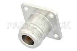
I unsoldered and removed the SO239 that is on the inside of the tuner. I replaced it with a Type N panel jack. You will need to saw/grind off one corner so that the cover will fit. The hole spacing is the same so you need not do anything to the mounting bracket. Resolder the center pin to the tuner input lead. Note, I found where mine was factory soldered to the stud sticking out of the board had a cold solder joint so I removed the lead, cleaned, fluxed, tinned and then soldered it.
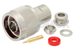
Lastly I made a Type N male to Type N male jumper about 16" long with RG58 to make the interconnection between board and cover This small loop makes working under the cover a breeze. The loop needs to be long enough to loop around the mounting bracket. Thankfully Icom offset these two connectors slightly so this works out perfectly. Don't worry about the RG58 ...it's too short to be lossy and is going to handle only 100 watts that the tuner is rated for with no problems.
The only reason why Icom didn't build the tuner like this is likely cost. As mentioned, the internal jack and the hole in the cover as offset, likely for this very type of connection. Engineers and RF guys are both a bit anal and would have otherwise lined these two up.
If you like PL239 / SO239 connectors, that's good for you, but I cannot stand them. Poorly designed, mechanically weak, not even weather resistant on their own. Type N connectors are a great design, mechanically solid and weather proof on their own (yes, for long term I tape them up with Scotch 23 and then Scotch 33). I used all silver plated connectors. If you are looking to save a bit of money you're fine to use the standard plating on the inside, but for the bulkhead you'd be wise to use a silver plated one. I added a dust cap to the N connector (also silver plated) to keep things tidy when not in use.
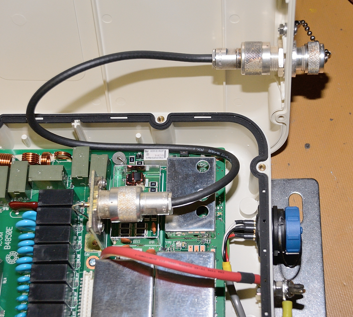
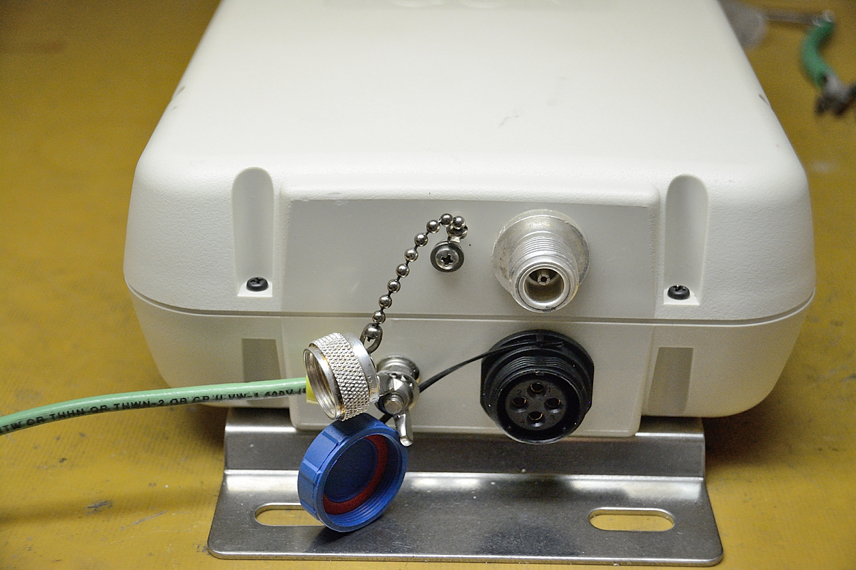
Finished - it looks great and is very friendly to use this way |
|
| The edges of the connectors were further sealed with a bead of high quality RTV, also I dabbed a bit on the screw heads since these are not stainless steel. It can be easily removed if the case hase to be opened, but after this mod that is highly unlikely for many years. |