|
Pixie is one of the simplest classic low power CW transceiver designs in world. Over years many variations have evolved. The present version is based on a design developed by a
French radio operator .
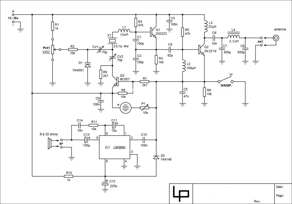
Our present project is capable of putting out a signal of 500-750mW on a frequency of 3.57Mhz in the amateur radio 80 meter bands.
The circuit can be split into transmit and receive:
Transmit: Pressing the key causes the set to go into transmit.
The frequency is generated by an oscillator designed around Q1. The frequency is determined by a fixed frequency quartz crystal of 3.579MHz. L1, CV1 and Pot1 enables very fine tuning of frequency.
Variable capacitor CV2 is active only during transmit and with the help of Q3 This provides an offset of about 700Hz from the receive frequency.
Q2 is the final power amplifier. It boosts up the low power signal to a level of around 500mW.
C7, C8 and L4 forms the low pass pi filter that cleans up the transmit signal and suppresses the harmonics of the required signal. This signal is then applied to the antenna. The buzzer gives an audible signal corresponding to the transmitted signal. It is
Called side tone. P1 controls the side tone level.
Receive: The receive section is direct conversion type. On releasing the key the set
goes into receive.
The Pi filter at antenna offers a bit of RF selectivity and rejects other signal present in ionosphere. Q2 the power amplifier transistor acts as a simple diode mixer. Q1 the crystal oscillator now acts as a local oscillator and provides a signal that is shifted from transmit frequency by 700Hz. When mixed with the incoming signal in the diode type mixer a resulting a very weak 700Hz audio signal is obtained.
IC1 is an operational amplifier based audio amplifier design. It boosts the 700Hz signal. This now level audio can be heard on headphones. Diode D2 mutes the audio amplifier in transmit.
The whole set is operated by a 12V battery. At these power levels and a simple half wave Dipole antenna it is not uncommon to work stations upto 300Kms.
Compiled by VU3WJM / Rahul |