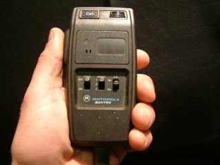
Motorola Syntrx.
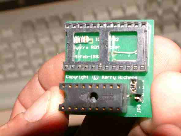
In 1997 I designed an eprom adapter board
to suit the syntrx. The schematic for these has been around in many forms
for a few years but no one had put a board on the market. I sold my boards
at cost to help local hams and some commercial companies. My board was
labelled with a copyright notice because I think little of others ripping
my artwork for commercial gain. At this point I need to say that the company
that reprinted my layout is not at fault and that RCS radio in melbourne
is a highly respectable company that has been around for many years they
would have not been aware that the client was not the copyright holder.
The really annoying thing is that If that guy had asked me for the originals
I probably would have given them to him.
If you buy one of these on ebay or at the Wyong
field day and it has RCS printed on it then you are unfortunately lining the
pockets of someone who does not have the right to reprint and sell my artwork.
The worst bit is that when I confrunted him at the Wyong field day where he
had a stand dedicated to selling these, His ony comment was that it's a simple
enough design of little significance.
Were that the case he would have drafted his
own !
Heres a picture of my adapter board printed
for me by Veltek in adelaide (1997)
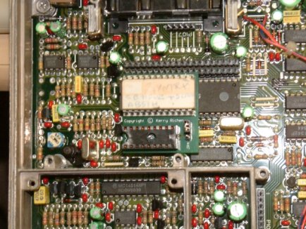
This is how it seats in the Syntrx with the
EPROM directly above the CPU
Anyhow, I probably wont make any more. and here's
why
The syntrx toggles the VCC line on the eprom
to read (remember that the original prom was an old bipolar). My board replicates
that which means it wont work with CMOS EPROMS.
one of the members of tha Albury amateur radio
club was on the team that designed the Syntrx radios way back (He ought to know
a thing or two). Anyway, he has laid out a very nice version that has an added
transistor to invert and divert the enable line to the chip select where it
belongs.
I believe that the Albury club is selling them
to raise club funds. If I track them down I will put contact details here.

Look Mum No Mike!
Yes It has been done before. But I like the idea
of placing all of the mods inside the radio. Here is my simple and somewhat
dodgy modification to allow the Syntrx to be used For APRS. The mod does a number
of things as follows.
1. Present enough current to the microphone power
regulator to convince the radio that the power switch is on.
2. A resistor to convince the PTT line to stay off unless commanded
by the TNC
3. A resistor to set the speaker volume control for monitoring
purposes.
4. Separation of PTT from mic line.
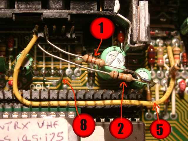
Heres the sequence of modifications to acheive the goal:
1 placement of a 120R resistor between R415 (+5volt side) and P107-5 convinces
the radio that it should be on
2. Placement of 1 10K resistor between the same +5v source as above and P107-6
Holds PTT high.
3. Removal of Resistor R424 isolates the cpu display data from the microphone
connector.
4. Removal Jumper JU405 isolates the PTT from the Microphone hi line on the
microphone connector (P102-6)
5. Placement of a wire between P107-6 and the end of R424 that goes to P102-4
makes P102-4 the PTT line.
6. Placement of a fixed or trimmer resistor between R79 and ground sets output
level.
7. The volume set resistor can be placed at the TNC end if reqquired it comes
out on P102-9
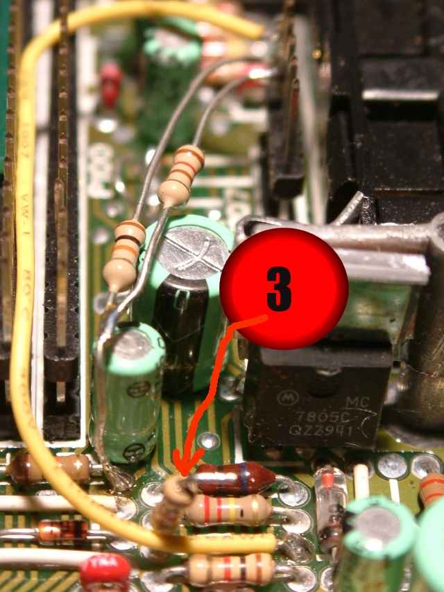
8. Placement of a link between JU402 and JU401 (the ends nearest to the CPU)
| The jumpers to remove are in the middle of this
picture |
Just one leg of the resistor is lifted |
|
 |
 |
 |
|
Syntx
Mic connector
|
Usage
|
Colour
(The Syntrx lead is standard)
|
Din Connector (Standard-TNC)
|
|
P102-4
|
PTT (was display data)
|
Slate
|
3
|
|
P102-5
|
Mic switch data
|
White
|
unused
|
|
P102-6
|
Mic Hi
|
Green
|
1
|
|
P102-7
|
0V
|
Black
|
2
|
|
P102-8
|
+5V
|
Red
|
unused
|
|
P102-9
|
Volume control
|
Blue
|
optional
|
|
P102-10
|
RX Audio
|
Orange
|
4
|
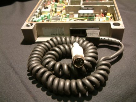
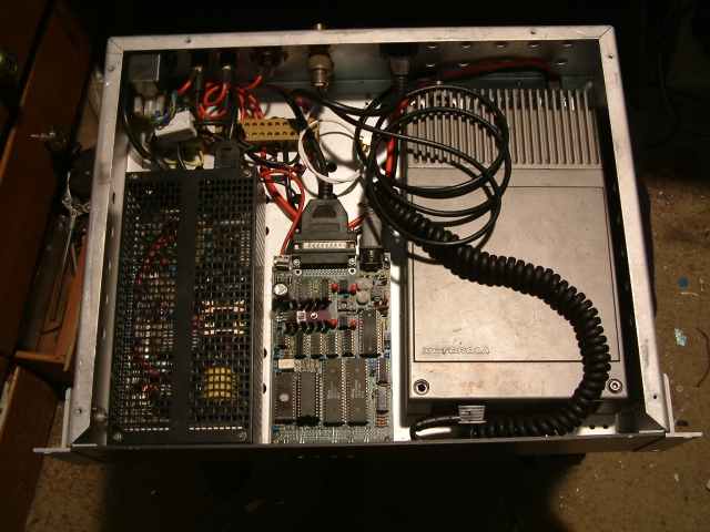
Here is my Syntrx APRS box.
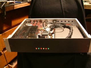
This consists of a Syntrx and an old TNC-2, all
powered by a battery backed Switchmode Power Supply.
Syntrx Roms.
I Will have these roms avaliable soon for UHF
and VHF to suit radios with type A and type B CPU's.
Very robust mobile radio's. I will have these
files ready soon soon!
| 1 |
70cm Ham |
|
| 2 |
Channel list for 70cm ham |
|
| 3 |
2m Ham |
SYN2MTR.rom |
| 4 |
Channel List for 2m ham. This is the same as the "ACT
RED" file for FM900 radios |
|
| 5 |
VHF APRS single channel Rom on 145.175 |
SYNAPRS.rom |
| 6 |
|
|
| 7 |
|
|
SYNTRACKER!
Here's my current project to make a robust APRS
system where the GPS engine, The Tiny track and the Max 232 line drivers are
all installed insid the Syntrx radio.
Again, Here is an over cooked and very fiddly
job where the effort does not nesecarily justify the final product. Because
it is my hobby I can't be accused of going too far. It would have worked just
as well if it was on vero board and installed in a tupperware box but it's in
the building that I derive my kicks!
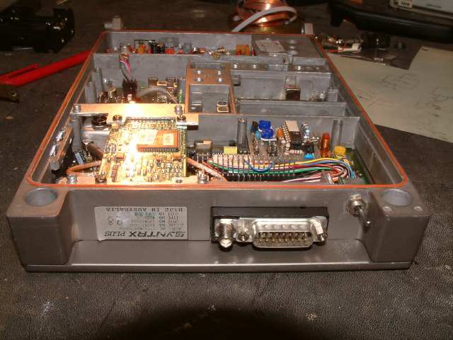

You can see the GPS engine is mounted on the
left on carefully cutout brackets that use the mounting points for the original
Motorola selcall board. The Tiny Track Clone (A board that I laid out) is positioned
above the Micro.

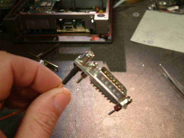
The original connector block was removed and
gutted to make way for a DB15 and the SMA connector for the GPS antenna. The
switch to the right toggles the serial lines so that in the normal position
the cable provides GPS data to a laptop for OZI Explorer (tm) etc.. and in the
other position allows configuring of the Tiny Track. The cable also provides
all led indicators up to the vehicle console.
The Max232 "not shown" also provides
programming for the Syntrx plus via the same db15 "NO RIB NEEDED"
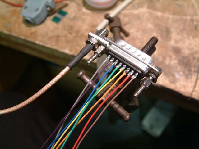
Thats the cool bit
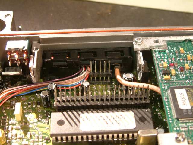
The cable breaks out into the radio nicely
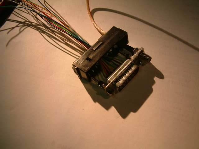
Here are some of the assembly pic's
More pics will follow showing the final rats
nest with the MAX232 board etc..
Still cool but not as neat as I would have liked.