Modifications for the Yaesu
FRG-9600
Picture

05-03-1999 FRG-9600 Discriminator
modification instructions
Yaesu FRG-9600 VHF/UHF radio
~~~ DISCRIMINATOR MODIFICATION ~~~
By Donald Gray G3YPL/ Ex ZL1AZC
© Copyright Donald Gray 1998
Disclaimer: The following is given in good
faith. I cannot be held responsible for any omissions or errors, or to any
damage caused to any radio howsoever caused....All care but no
responsibility!!!!
Tools required:
- cross head screwdriver
- 25 watt, fine tip soldering iron
- tweezers or needle tip pliers
- side cutters
- needle files
- sharp knife (to cut one pcb track)
- a small container to hold screws & washers.*
* The last item is very important. There are many screws
to remove. It is all too easy to loose one. Make a habit of ALWAYS putting the
removed screws & washers into a small container such as a 35mm film
container, cup, coffee jar lid etc. NEVER ever leave them loose on the table or
bench.
Components required:
- 1 x .01 capacitor
- 1 x small cable tie
- Approx 12 to 18 inches of smallish diameter Audio cable (coaxial screened
essential)
- 1 cup of coffee
To gain access to the NFM discriminator on this radio is easy BUT only do it
if you feel capable of doing one very fine solder connection....
Basically what you have to do is connect a short length of audio coax, via a
small capacitor, from pin 14 of the mixer/nfm
discriminator chip (MC3357P). to an unused socket on the back
of the radio. There are several sockets on the back and I have used the "MPX"
socket on my radio because I will never want to put a stereo multiplexer on it!
The instructions below relate to the MPX socket. You can choose any of the
sockets that you will not need but you must cut the tracks
leading to that socket before adding soldering the coax
thereto!
Step-by-step Instructions
- Disconnect power and other cables at the back.
- Remove top and bottom covers.
- From the top, locate the N.F.M. board (4.25 inches [115mm] from the back
panel)
- Very carefully solder one leg of the 0.1µF capacitor to the solder side of
the pcb where pin 14 pokes out. Be careful to correctly
identify this pin AND be careful with the soldering, it is a fine bit of
soldering and is easy to short out this to the adjacent pads. CHECK
and double check that you have done a good "clean" solder job
here -It's vital to be very careful - I cannot stress this enough!
Leave thecapacitor hanging in the air for the moment...
- Use a small needle file to drill a small hole in the top portion of the
nfm pcb where there are no tracks. through this hole, thread a small cable tie
and leave in situ for the time being. (Later, you will secure the audio coax
here. See step 9 below.)
- With a sharp knife, scrape a section of the solder resist from the top,
right hand "Earth" track (as seen from the solder side of the pcb) and tin it
with solder (To confirm that you have the correct track, it is the track also
connected to the can of the xtal on that board!)
- Prepare the coax by:- (a) Stripping back the outer insulation by about one
inch. (25mm), twist the shielding together and tin it for about .25 inch [6mm]
and then trim it down to this length. (b) Stripping back the inner by about
1/16 inch (2mm) and tin the inner conductor.
- Solder the screen of the coax to the earth track so that it will present
the inner conductor very close to or touching the free leg of the capacitor.
- Now clamp this coax cable into position using the cable tie (as mentioned
in 5 above) to secure it.
- Solder the inner conductor to the free end of the capacitor
- Orientate the radio so that the front panel is facing you and looking into
the radio from the top, thread the free end of the coax to the bottom, by way
of gap between the main pcb and the case at the back, right hand side (near
the two white connector plugs) Tuck the coax under the big choke (the thing
that looks like a transformer). BE CAREFUL not to put any strain on the coax.
Leave a little slack ...
- now turn the radio upside down and orientate it so that the dial
is facing your right. The coax should be poking up at the left hand
side nearest you! To use the "MPX" jack socket as the access point:-
- Identify the 3 mounting pins of the MPX jack. They are 2 5/8 inch [65mm]
from the edge facing you, of the main pcb . The pin on the left is the earth
(ground) pin. The centre if the "live" pin and the right pin is not used
electronically (only as a mechanical mounting point and is ignored in this
mod)
- Carefully cut the track leading to the centre "live" pin about half way
along its length (This removes the unused "MPX" signal to the jack socket.
- Prepare the audio coax appropriately and solder the screen to the earth
pin and the inner core to the middle pin. Replace the top and bottom covers,
making sure that there is no strain on the coax and that it is not being
"pinched" by the covers.
IMPORTANT - Add a "MOD NOTE to the inside of the radio and
also in the instruction book:-
- a small self adhesive label stuck to the metal screen on the underside of
the pcb with words to the effect : "21 Jan 98 - track cut to remove mpx and
coax added to give access to the NFM discriminator output"
- Similar label on the back denoting the MPX now to be "NFM Discriminator"
- If you have a circuit diagram, note the change also thereon!!!
The discriminator output is at a fixed level (about .7 volt) and totally
isolated from the volume control - the setting of the volume control will not
effect the discriminator level. The squelch control WILL cut in and out on the
discriminator line in the same fashion as on the normal audio.
BTW: e-hum, why do you want a discriminator output on the radio
anyway?:>)
05-03-1999 How to expand the frequency range
og the FRG-9600 from 60-905 to 20-950 MHz
Waring! Do not
attempt to do this if you do not feel confident when using soldering equipment.
Do not blame me if you screw up your receiver or do any damage to anything you
are using.
First write down all the stored frequencies, in case the
memories of the receiver get lost. Then turn it off and disconnect all
cables.
I will not explain how to open the case. If you can't find it out
by yourself, you sure won't be able to do the work.
What you see above,
is the Printed Circuit Board (PCB) of the FRG9600, seen from the
bottom.
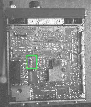
What you need: 1 resistor 1 KOhm 1/4 or 1/2 Watt, 3 pieces of
wire, soldering iron GREEN SQUARE: This is the 1 KOhm resistor, soldered between
the pin # 1 (Counting from the top) and the nearby ground terminal of the pin
array marked J8001/J9001, next to the black rubber piece.
Beware, the the
sensitivity is not very good in the expanded frequency range, but it is still
usable. Also interference from the computer might matter. I've also noticed that
some receivers might be better, others might be less good, depending on how the
front-end is aligned. I'm working on this, so stay tuned :-).
Now turn
around the opened FRG9600, so that you can look inside from the
top.
Locate the BAND UNIT. This is the vertical circuit board with a
metal frame, closest to the front panel. Next to it, on the main Circuit Board,
there is the text BAND UNIT written. You have to solder the 3 jumper wires on
this Band Unit.
When you look at the front of the Band Unit, near its top,
you will see 6 empty holes, marked on the below drawing with x.
                               (Top)
               ------------------------------------
              |                                    |
              |   x.......x          x.......x     |
              |     _                   x.......x  |
              |    |S|                             |
              |    |0|                             |
              |    |1|                             |
You have to solder the jumpers marked x.....x, either by connecting the
soldering points on the back, or inserting the jumpers through the holes on the
front.
If you have the switch S01 inserted, this must be on the OFF position.
Usually this switch is not installed, its use is to limit the frequency range of
the FRG, probably for some countries who required it.
Now check your
solderings. They must be clean, and must not touch the nearby pins. Check also
that you have not left any metal chips from the jumpers or the soldering lead
inside the receiver. Close the box, connect the cables and turn it on.
With
the dial you can now select all frequencies between 0.0000 and 999.0000 Mhz, but
only the range 20.0000 - 950.0000 will be operational.
Waring: On
some frg's the frequency on the display is off by 27.250 Mhz from the real
frequency you are receiving on the low band, i.e. if you want to listen to
50.000 Mhz you have to enter 22.750 Mhz.
05-03-1999 Accessing the discriminator
output on the FRG-9600
The discriminator output is needed if you
want to decode digital data, like the POCSAG code used by common beepers. On
this output you have raw audio, before it passes through the amplifier, tone
control etc.
This audio will not be affected by volume and tone control,
but it will be affected by the squelch control.
What you need: 1
Capacitor 0,1 uF, a piece of coaxial cable, soldering equipment.
First
write down all the stored frequencies, in case the memories of the receiver get
lost. Then turn it off and disconnect all cables.
Disconnect all cables
from the back panel.
Open the top of the FRG9600.
Locate the
Narrow FM board, this is about in the center of the FRG, about 110 mm from the
back panel.
On this board there is an IC MC3357P. Locate the pin Number
14 and solder one leg of the capacitor to the soldering point where this pin is
connected.
Pin number 14 is the third pin of the top row of the IC,
starting from the side where the IC has the notch.
Now solder the coaxial
cable: the inner conductor has to be soldered to the second leg of the
capacitor, the outer conductor has to be soldered to a place connected to
ground, somewhere near the capacitor. Now use some insulating tape or cable tie
to fix the capacitor and the cable in place, so they don't move around too
much.
That's it. Now you can connect the other end of the cable to some
unused plug on the back panel of the FRG, and this will be your discriminator
output.
Waring: Do not attempt to do this if you do not feel
confident when using soldering equipment. Do not blame me if you screw up your
receiver or do any damage to anything you are using.
Now check your
solderings. They must be clean, and must not touch the nearby pins. Close the
box, connect the cables and turn it on.
05-03-1999 900Mhz + UP
Selectivity
WATCH OUT: This step is not as simple as the previous
one, You really need a lot of caution and ability with the soldering
iron.
We now will retouch a little the local oscillator, in order to able
to improve tuning of the frequencies above 900 mhz, for which the receiver was
not adjusted in the factory.
The tuning circuits are inside the metal box
next to the antenna plug, manufactured by SHARP.
Inside here there are
two oscillators, for the UHF and VHF. We will adjust a link in the UHF circuit,
to enable it to work on slightly higher frequencies.
- Open the lid on the metal box. Inside there's the circuit in the following
figure.
- Tune the FRG on 460 Mhz.
On the PLL unit, below the IC MC 145158, you
can see the pin marked TP02. With a digital tester measure the voltage on this
TP02, it should be around 1,1-1,5 V. The PLL unit is, among the two high
printed circuits, the one closer to our metal box, next to it there's written
'PLL UNIT'.
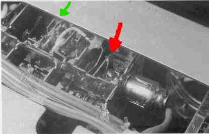
- On the figure, next to the red arrow, there's a horizontal copper strip,
with another vertical copper strip strip soldered at its end. These two strips
make an angle of 90°.
With a very fine tipped soldering iron melt the
soldering which connects these two strips, and bend the vertical strip a bit
towards the beginning of the horizontal strip, to shorten a bit this
loop.
A fraction of a millimeter (about 0,5 mm) should be enough.
Measure again the voltage on TP02, receiver tuned on 460 Mhz. The voltage
should be now around 0,6 V. If not, you can still make small adjustments to
the copper link. Now, with the FRG tuned on 950 Mhz, you should have a voltage
on TP02 of about 30,5 V.
- Now, let's improve the reception sensibility in this high band.
Connect
the digital tester on pin nr. 12 of the IC MC3357, the FM
discriminator.
The voltage should vary from about 0,6 V with no signal
received, to about 1,2 V with maximum signal, with the squelch
unblocked.
Tune the receiver to a frequency around 460 mhz, which has to be
busy with some signal. (A repeater output would do fine)
Next to the
green arrow in above figure there are some pairs of copper strips, which make
some resonating links. With a little NON INDUCTIVE screwdriver adjust these
strips a little closer or farther from each other, until you read the maximum
value on the tester, always whlie receiving the same signal.
Repeat
this step also on higher frequencies, the corrections on the copper links must
be very fine.
Now the reception on 900 and more mhz should be much
better.
Have you any tips, trick or modifications you can't find
here, please E-mail them to me, or use
the mail form.
Can't you
find a mods, please don't e-mail to me. All mods i have is listed on this
site. Back to start
page |