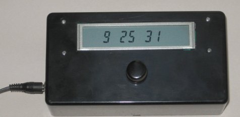
Chiming Clock
The idea of this project is an LCD clock that chimes on the hour and half hour. It was conceived after my wife expressed a liking for the sound of a rooster crowing from a friend's Palm. There are many ways to produce sound from a microprocessor based project. Beyond simple buzzers and beepers and perhaps square-wave generated tones, things get complicated fast. Not that I'm an expert, there may be ways to do it that I don't know about.
The rooster sound runs for about 9 seconds and takes 1.6 MB of memory for a WAV file. This reduces to 150 KB when compressed into MP3. This could be further reduced if lower quality parameters were used, but already I could see that storing the sound in this way and being able to play it back would make the project way too costly and complex for me.
Years ago I experimented with a Winbond chip that recorded a few seconds of audio, the ISD1416. I still had one in my parts box, and it would be ideal for this project. Unfortunately Winbond does not appear to make these chips anymore*, but a search would probably reveal other similar chips that could be used instead. I appologise for documenting a project based on an obsolete part, but I hope the idea is still useful.
The 1st schematic shows the microprocessor and clock components. Nothing new here, my appliance timer is very similar. Again I use a KTM-S1201 LCD display, which has 12 numeric 7-segment digits. You could easily substitute a different display and change the code accordingly. Also I use a CTS-290 encoder as the only control, and an NJU6355 real time clock.
(The NJU6355 is no longer available. I used a DS1302 in this project, it could be used as a substitute here.)
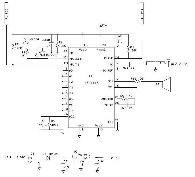
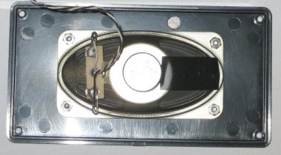
The 2nd schematic shows the ISD1416 hooked up to play back under control of the microprocessor. A pulse on PlayE triggers the chip to play back the entire sound on the hour. PlayL is pulsed for two seconds to play the 1st part of the sound (a bong) on the half-hour. Recording is done once using S1, a tiny pushbutton on the circuit board. Plug in the sound source, press and hold S1 to record the sound, and release when the sound is finished. I had to place a resistor, R10, in series with the speaker to lower the volume which was surprisingly loud.