| GS-36 B = 4CX400A |
| Tetrode |
| The GS-36B tetrode is designed for power amplification in distributed-gain amplifiers and single-sideband signal amplifiers at frequencies up to 75 MHz, and for power amplification at up to 500 MHz in RF equipment |
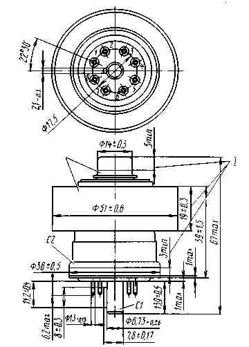
| GENERAL Cathode: indirectly heated, oxide-coated. Envelope: metal-ceramic. Cooling: forced air. Height: at most 67 mm. Diameter: at most 51 mm. Mass: at most 220 g. |
|
| 1 - grid; 2, 4, 6, 8 - cathode; 3, 7 - heater; 5 - no connection; C1 - grid 1; C2 - grid 2; A - anode; I - contact surfaces |
|
||||||||||||||
|
||||||||||||||||||||||||||||||||||||
|
||||||||||||||||||||||||||||
|
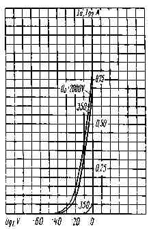
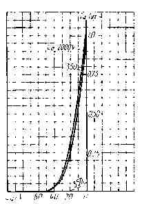
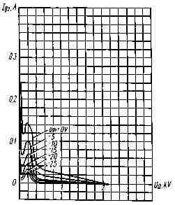
| Averaged Anode-Grid and Grid
Characteristic Curves: Uf = 6.3V; Ug2 = 250V; _____ Ia; - - - Ig2 |
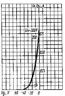 |
| Averaged Anode-Grid and Grid
Characteristic Curves: Uf = 6.3V; Ug2 = 275V; _____ Ia; - - - Ig2 |
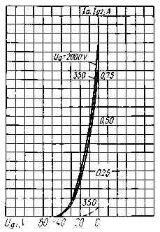 |
| Averaged Anode-Grid and Grid
Characteristic Curves: Uf = 6.3V; Ug2 = 300V; _____ Ia; - - - Ig2 |
 |
| Averaged Anode-Grid and Grid
Characteristic Curves: Uf = 6.3V; Ug2 = 325V; _____ Ia; - - - Ig2 |
 |
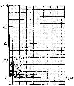
| Averaged Grid-Anode Characteristic Curves: Uf = 6.3V; Ug2 = 250V |
 |
| Averaged Grid-Anode Characteristic Curves: Uf = 6.3V; Ug2 = 275V |
 |
| Averaged Grid-Anode Characteristic Curves: Uf = 6.3V; Ug2 = 300V |
 |
| Averaged Grid-Anode Characteristic Curves: Uf = 6.3V; Ug2 = 325V |
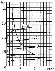 |
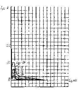
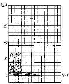
| Averaged Anode Characteristic Curves: Uf = 6.3V; Ug2 = 250V; _____ Ia; - - - Pa max |
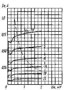 |
| Averaged Anode Characteristic Curves: Uf = 6.3V; Ug2 = 300V; _____ Ia; - - - Pa max |
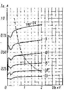 |
| Averaged Anode Characteristic Curves: Uf = 6.3V; Ug2 = 325V; _____ Ia; - - - Pa max |
| Drop me an E-mail on the price - I guarantee the lowest one ! |