|
VHF-UHF Portable Yagi-Uda
Antenna Design
and Construction Notes by XE1MEX

Introduction
Since it is very difficult to get a commercial VHF-UHF portable antenna in
my town (like the famous Arrow), I decided to build a homebrew antenna as
I did it in the past with most of my old HF and VHF antennas. My personal
commitment was to get it ready for my holidays in Cancún (May 2 to May 8,
1999) in order to operate from the grid square EL61 using the AO-27
satellite. The antenna performance was excellent and a lot of satellite
contacts were made during my stay in Cancún and surrounding areas. Since
then I have used it from my home and every time that I have a chance to be
out of my home grid square (EK08mu). In 1999: EK09, EL00 and EL61; in
2000: EL60 and EL61; in 2001: EL61, EL50, EL51, EK06, EK07 and DK96; in
2003: EL61, EL60, EK58 and EK68.
I have succesfully tested this antenna with the satellites
AO-27,
SO-35,
UO-14,
FO-20,
FO-29 and
AO-10 ...please
see the updates and photos below.
Software
The GWBasic software program that I used to design my double Yagi-Uda for
VHF and UHF was developed by Guenter Hoch, DL6WU.
It is available for download directly here (80 kB):
Download Yagi-Uda design
program by DL6WU
In case you get a password or login
request to download the program, please let me know by e-mail..I will send
the compressed file directly to your e-mail address. Sometimes the server
rejects the download request.
In order to use this program please follow
these instructions:
1. Decompress all files contained in antenne.zip into a new folder in your
PC.
2. With the windows explorer try to run the file Antdl6wu.bas
3. If a dialog box appears asking you for the program to run it, click in
"other" and then select the file Gwbasic.exe which is available in the new
folder that you created.
4. The program should be running now within Windows 95, 98, 2000, XP or NT
in a separate window. Please do a click just ahead of the question Y/N and
type Y plus enter. You are in; just follow the instructions and give it
your design parameters.
Construction
Details
Assuming that you have downloaded the program and it is running properly,
what I can share with you (just to save time) are the program results for
the specific parameters and material that I had available at home:
- Center VHF frequency: 145.850 MHz
- Center UHF frequency: 436.800 MHz
- Number of elements: 8 in UHF (10.5 dBd
gain), 4 in VHF (6.46 dBd gain)(longer and heavier than the Arrow but
still portable !!)
- Boom diameter: 22 mm
- Elements and gamma pipe diameter: 9 mm
- VHF elements lenghts: R=1017 D=972
D1=917 D2=906
- VHF elements spacing: R to D=380, D to
D1=162, D1 to D2=370
- UHF elements lenghts: R=349 D=325
D1=303 D2=298 D3=292 D4=287 D5=285 D6=282
- UHF elements spacing: R to D=127, D to
D1=54, D1 to D2=123, D2 to D3=148, D3 to D4=173, D4 to D5=193, D5 to
D6=207
- The reflectors are mounted 15 mm (VHF)
and 25 mm (UHF) from reflector center to the boom edge (thanks to XE1YJS
for his correction !- Feb 2, 2002).
REMARKS: All dimensions are in
millimeters, all elements are made of aluminum pipe, R=reflector,
D=driven, D1 to D6=directors, all spacing between elements is from center
to center, elements are mounted over the boom (not through
the boom) and they are not isolated to the boom.
I used a teflon rod (430 mm long, 100 mm inserted into the boom edge) as
arm/hand support...you can use whatever you have -non conductive of course-.
I used those aluminum pipe diameters
because they were available at home, but I strongly recommend you to use
thinner pipes (perhaps rods) to make a not so heavy antenna...your arm
will thank you in case you like to have long radio contacts. If you do so,
do not forget to re-calculate with the actual elements and boom diameters.
The Gamma
Match
Now let´s go to the "difficult" part...the matching between coaxial cable
and feed point of the driven elements. Since this is a portable antenna to
be used very close to the transceiver, I decided to ignore the losses of
the normal BELDEN RG58 A/U coax cable because I put just 1200 mm of coax
between radio antenna connector and each driven element.
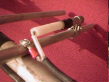
Also I decided to follow the old and problem free matching method known as
gamma match. I have always used it with excellent results, and because I
do not put any kind of additional capacitors but I use a bare piece of RG8
or RG213 or RG214 as coupling capacitor which is inserted into an small
piece of aluminum pipe. This pipe has an aluminum band which makes the
connection between the sleeve and one arm of the driven element. The bare
coax means a piece of coax cable without the external plastic cover and
without the shield screen...well, I think it is better to see these
pictures which tell you more than a thousand words:


 (Feb.18, 2001): The most frequently asked question
from the friends that have duplicated this antenna is related to the gamma
match. You asked for it many times, so...if you need a simple drawing
please click here or
in the thumbnail:
(Feb.18, 2001): The most frequently asked question
from the friends that have duplicated this antenna is related to the gamma
match. You asked for it many times, so...if you need a simple drawing
please click here or
in the thumbnail:

Of course you can use any other matching
method, but in case of the gamma, here is some data that will save you
time:
- VHF: gamma aluminum pipe lenght=150 mm,
total bare coax lenght=230 mm, bare coax lenght into the alu pipe=68 mm,
alu band (making short circuit between gamma "rod" and driven element)
placed at 310 mm from center of boom, separation between gamma "rod" and
driven arm=30 mm (center to center).
- UHF: gamma aluminum pipe lenght=50 mm,
total bare coax lenght=68 mm, bare coax
lenght into alu pipe=20 mm, alu band placed at 84
mm from center of boom, separation between gamma "rod" and driven arm=20
mm (center to center).
- Many thanks to
Marcin Korona, SP8UFX for his remarks to correct a couple of important
UHF gamma dimensions ! (May 15, 2001).
In case you want to do a fine adjustment
to the SWR and assuming you have the proper SWR meter, look for minimum
inserting or extracting the bare coaxial part and/or moving back and forth
the shorting band.
The Reward
Well, after so much effort the good news...if you duplicate the described
antenna, I can guarantee that you will get an SWR of less than 1.3:1 in
both center frequencies and not more than 2:1 in the band edges.
I could not measure the front gain but it should be close to the
theoretical; anyway, just aim your beam to the
AO-27,
SO-35,
UO-14,
FO-20,
FO-29 or
AO-10 and I
am sure that you will be satisfied with its performance.
Ok, as you see I did not write anything
about the diplexer. It is just because I use two radios. I am going to
build a diplexer soon; if it works as expected I will publish here the
circuit diagram and its construction details.
I hope you enjoy the construction of this
antenna as much as I did...73´s de XE1MEX....Alex
|


