|
|
|||
| http://www.qsl.net/ta6ia/documents/ANTENNAS | |||
| . | |||
|
SWISS QUAD ANTENNA |
|||
|
Creation : August 2001 Subject : SWISS QUAD Antenna, issue 10 Alain Miqueu, F6ITV Which monoband directional antenna can provide a good gain, a good F/B ratio, being not to large and mechanically within hamradio skill? As it is used to say, it's a process that consists in searching the best compromise. q This excludes high-gain and long-boom Yagi that are very large and heavy. q A 3-element Yagi could be suitable regarding performances but to me it's still too large. q A 2-element cubical quad could be suitable regarding performances and sizes, but mechanically it's rather complicated and fragile. q The well-known Mr Baumgartner, HB9CV, has implemented a 2-element tubing antenna that has the both elements fed with such a phasing that it gives it better performances than a 2-element Yagi. In Europe the HB9CV antenna is widely used in VHF and UHF portable experimentation but also in HF. It has a lot in common with the ZL Special, see W4RNL : http://www.cebik.com/hb.html q HB9CV also transposed his feeding system to the 2-element cubical quad, this allowed him grounding the both loops, a genius idea for a unique model, he called it SWISS QUAD. It took me fancy at the time I saw it, even if it seems mechanically more complicated than a 2-element Yagi, in my opinion its construction is easier than a classic quad owing to its all-grounded feature. To day I have built two Swiss Quad, one for 28 and another one for 50 MHz. So I take web opportunity in bringing this benefit to who is interested in building this antenna because it's really fancy and it will give you excellent DX performances together with the satisfaction of its construction. Notes  q I remember that in 1990, a JA OM has informed me that experiments have been carried out on 10m to add parasitic tubing elements to the Swiss Quad (Swiss Quagui ?) and also to make stacked arrays with the resulting antennas. q Also I remember that in the 90's the Japanese Company TET has commercialised this kind of antenna  for the 144MHz band. CLAIMED PERFORMANCES q Gain against a dipole at short distance 6 to 7.9 dB q Gain against a dipole at long distance 12 to 14 dB q F/B at 15 km 15 dB q F/B at 1000 km 10 to 12 dB q F/B at 3000 km 18 to 24 dB DIMENSIONS At first, my warmest acknowledgement to F3XY, R.Piat, author of a very well known book 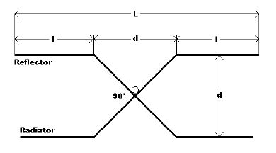 within the French-speaking community, "LES ANTENNES". Actually, F3XY provided me with an original document, which I was looking for since a long time, concerning the Swiss Quad antenna by Rudolf Baumgartner, HB9CV. In spite this document is in German together with my poor knowledge of Goethe's language, fortunately texts applying to calculations stay definitively understandable, so I am know in position to relate how HB9CV has defined the quad perimeters of his antenna. q One knows that the loop effect make to resonate below the operational frequency an antenna which perimeter is equal to 1wl. So, a correction factor has to be applied to a quad perimeter in order it resonates on the operational frequency, HB9CV uses a factor of 1.12wl. q HB9CV gives oneself a 5% difference between the reflector and the director perimeters. q At least, the reflector has to be cut out in order to have its resonance 2.5% below the operational frequency and the reflector 2.5% above. So it simply leads to the following results: q Reflector perimeter: 1.12 * 1.025 = 1.148 wl  q Director perimeter: 1.12 * 0.975 = 1.092 wl Due to the specific geometry of the antenna, the length data seem difficult to determine. But when watching at the opposite drawing it's easy to deduce what are the length elements required for the construction. The loop perimeter is P = 2*(L + H) with, H = Height ; L = 2*l + d = width ; d = loop spacing CALCULATION HELP In order to avoid boring length calculations regarding the band, I developed the opposite EXCEL spreasheet which greatly facilitates the job. Download the chart tool (6 ko) : SQc.zip The tool is very flexible, it allows changing the frequency (CW or SSB centred), modifying the various coefficients (lambda fraction) applicable to the spacing and the loop perimeters and after final decision to freeze as constants, the height H and the spacing d. CAUTION, modification of coefficients is a facility provided only to see how they act on antenna dimensions. Modelisation is the only tool that can tell how modifications influence antenna performances. It's obvious that the accuracy of the figures results from theoretical calculations and that they can be rounded without any problem. CONSTRUCTION Following some requests for clarifying text and photos, I give hereafter a description concerning the SQ28MHz I constructed. It's a light version that has been under several bad weather influences, it was removed after 5 years (1988-1993) operation (see 10m dxcc entities) and it has demonstrated its serviceability. Obviously other tubing and/or wire diameters can be used because all the customisations will be automatically taken into account during the antenna resonance implementation. Some drilling and diameter informations are not provided. They depend on the material and the hardware you will use. Sizes Determination of d It's recommended choosing a loop spacing equal to 0.1 lambda Determination of H H, the loop height, is the same for the reflector and the director. H is theoretically determined as being a 1/4 perimeter of the reflector loop, which is the longer. I never found any precise information on this topic but, in practical, H is slightly lengthened and on 10m I chose a h = 0.26 coefficient in order to get a rounded H value of 3.15m. Determination of L and l When rounded H and d values are entered in the concerned cells of the chart, then you will get for each loop the L and l values. Antenna Assembly It's very important to respect the general symmetry of the loops but also the length difference between loop perimeters. Vertical Elements I used a 1mm2 supple-sheathed cable made of several thin copper wires (100w suitable) and having an H length, soldered terminals included. Horizontal Elements After d, H, L and l determination, it's time to come to the making of a horizontal element. For each horizontal element I used a central section made of aluminium squared tubing, 50cm long and 20x20x1.5mm. Two sections of aluminium tubing, 1m long and 16mm diameter, can slide inside the squared tubing in order to adjust the d spacing and the other end is bent at 45° on a length of 25cm. Determine the correct position of these sections inside the squared tubing, drill where it's necessary in order to fasten them with screws, washers, nuts and inside wedges if necessary. (photos). Assembling two horizontal elements makes top and bottom of the loops. An OM easy to do aluminium special part ensures a reliable 90° crossing between two horizontal elements and the mast as well. (photos). Some advises: q Take care over 90° and 45° angles q Check that top and bottom horizontal assemblies are identical. On the ground, put them one over the other and compare. q Perform the involved corrections In order to ensure a tension of the vertical wired elements connected to the end of the l elements, I highly recommend bending slightly, up or down depending on their location, the 25cm-section bent at 45°. In order to adjust the loop perimeters during antenna resonance implementation, the l elements are made of 12mm-outer-diameter aluminium tubing, therefore they can slide inside the 25cm-section 16mm-diameter bent at 45° tubing. The ends of the bent sections are sawed in the length way by 3cm maximum. A clamping ring will allow locking the l element. (photos) Feeding Case q The case is made of an insulated material. q Two opposite side of the case are fit with a rubber seal adapted to the diameter of the gamma rod (photos) q An aluminium sheet is installed at the bottom of the case, it aims at grounding an SO239 by means of a channel section (photos) q The case is fastened to the squared tubing with screws, washers and nuts. It must not make any trouble to the pass of the vertical mast. Dual Gamma q The distance between the dual-gamma and the loop is about 30 to 35mm (outer to outer) q The dual-gamma is made of two aluminium rods, 1m long and 2mm diameter (not crucial) q The two rods are drilled at one end, these ends slide inside the rubber seals and then are connected together by means of an aluminium corner plate 10x10x1.5. (photos) q On 28Mhz, two capacitors in parallel - variable 60pF + fixed 60pF - are connected between the dual-gamma centre and the output of the SO239. q The sliding short-circuits are made by forming an aluminium flat part 10x10x1.5mm, the centre part is tightened by means of screw, washers and butterfly nut. (photos) Mast It is made of two TV stackable sections, 2m long and 40mm diameter. Drillings have to be accurate because they must perfectly agree with the top and bottom loop assembly ones. Hardware/Water-resistance It's highly recommended using stainless steel hardware of a very good quality and also using seal mastic where it's necessary. 5-years-in-service corrosion is highly visible on the photos. LOOP PERIMETER ADJUSTMENT STRATEGY q After H and d freezing, I have sought what is the value of frequency shift that gives L lengthened by 1cm or in other words P by 2cm and l by 1/2cm. This data will be very helpful to move/correct the resonant frequency. q Modifying each l element by the same value will adjust the resonant frequency and will keep roughly constant the difference between the loop perimeters. RESONANCE IMPLEMENTATION After antenna assembly and when it is in testing situation: q Place the dual-gamma short-circuits close to the maximum. q Place the 60pF variable capacitor at its maximum value. q Look for the frequency where the SWR is minimum. q To reduce SWR adjust the variable capacitor. q If necessary move slightly (by 5cm steps) each short-circuit toward the antenna centre. q To reduce again the SWR adjust the variable capacitor. q By starting again several time the above procedure you will find a frequency range where the SWR is close to 1:1. q One can deduce that the central range frequency is the antenna resonant frequency. This first adjustment is normally easy to get, but it doesn't take into account the difficulties in reaching physically the adjustment points. Hi! q According to the frequency shift data given by the chart tool (see above), modify the 8 l elements by the same value in order to shift the resonant frequency to the required one q Normally this modification affects the previous adjustments of the dual-gamma. Adjust the variable capacitor, if the previous resonant frequency was very near the involved one, it could be enough. q It's possible that you would have to start again the global adjustment procedure. Be patient! PUTTING A STOP For humidity reasons it will be necessary to replace the variable capacitor by a fixed one having a low temperature factor and suitable with the operating power. This entails to remove the capacitor set and to be able to estimate accurately its value or better to measure it. I preferred to place a capacitor equal to approximately the 3/4 of the estimated value and to test several values in parallel up to get the previous SWR and bandwidth. Following my experience on the 50MHz version that allows an easy access to the adjustment points owing to its small size, an accurate adjustment of the dual-gamma is the best way to optimise the SWR together with the bandwidth. In fact, the best short-circuit locations are obtained when the gamma length toward the reflector is longer than toward the director. After the antenna installed at the final location, don't forbid that probably you would have to start again the adjustment procedure. After all this is true for any kind of antenna |
|||
|