When transmission lines are used with a transmitter, the most common load is an antenna. When a transmission line is connected between an antenna and a receiver, the receiver input circuit is the load, not the antenna, because the power taken from a passing wave is delivered to the receiver.
Whatever the application, the conditions existing at the load, and only the load, determine the reflection coefficient, and hence the standing-wave ratio, on the line. If the load is purely resistive and equal to the characteristic impedance of the line, there will be no standing waves. If the load is not purely resistive, or is not equal to the line Z0, there will be standing waves. No adjustments can be made at the input end of the line to change the SWR at the load. Neither is the SWR affected by changing the line length, except as previously described when the SWR at the input of a lossy line is masked by the attenuation of the line.
Only in a few special cases is the antenna impedance the exact value needed to match a practical transmission line. In all other cases, it is necessary either to operate with a mismatch and accept the SWR that results, or else to bring about a match between the line and the antenna.
Technical literature sometimes uses the term conjugate match to describe the condition where the reactance seen looking toward the load from any point on the line is the complex conjugate of the impedance seen looking toward the source. A conjugate match is necessary to achieve the maximum power gain possible from a small-signal amplifier. For example, if a small-signal amplifier at 14.2 MHz has an output impedance of 25.8 - j11.0 ohm, then the maximum power possible will be generated from that amplifier when the output load is 25.8 + j11.0 ohm. The amplifier and load system is resonant because the ±11.0-ohm reactances cancel.
Now, assume that 100 ft of 50-ohm RG-213 coax at 14.2 MHz just happens to be terminated in an impedance of 115 - j25 ohm. Eq 11 calculates that the impedance looking into the input of the line is 25.8 - j11.0 ohm. If this transmission line is connected directly to the small-signal amplifier above, then a conjugate match is created, and the amplifier generates the maximum possible amount of power it can generate.
However, if the impedance at the output of the amplifier is not 25.8 - j11.0 ohm, then a matching network is needed between the amplifier and its load for maximum power gain. For example, if 50 ft of RG-213 is terminated in a 72 - j34 ohm antenna impedance, the impedance at the line input becomes 35.9 - j21.6 ohm. A matching network is designed to transform 35.9 - j21.6 ohm to 25.8 + j11.0 ohm, so that once again a conjugate match is created for the small-signal amplifier.
Now, let us consider what happens with amplifiers where the power level is higher than the milliwatt level of small-signal amplifiers. Most modern transmitters are designed to work into a 50-ohm load. Most will reduce power automatically if the load is not 50 ohm—this protects them against damage and ensures linear operation without distortion.
Many amateurs use an antenna tuner between their transmitter and the transmission line feeding the antenna. The antenna tuner’s function is to transform the impedance, whatever it is, at the shack-end of the transmission line into the 50 ohm required by their transmitter. Note that the SWR on the transmission line between the antenna and the output of the antenna tuner is rarely exactly 1:1, even though the SWR on the short length of line between the tuner and the transmitter is 1:1.
Therefore, some loss is unavoidable: additional loss due to the SWR on the line, and loss in the antenna tuner itself. However, most amateur antenna installations use antennas that are reasonably close to resonance, making these types of losses small enough to be acceptable.
Despite the inconvenience, if the antenna tuner could be placed at the
antenna rather than at the transmitter output, it can transform the 72 - j34 ohm
antenna impedance to a nonreactive 50 ohm. Then the line SWR is 1:1.
Impedance matching networks can take a variety of physical forms, depending on
the circumstances.
This section describes methods by which a network can be installed at the antenna itself to provide matching to a transmission line. Having the matching system up at the antenna rather than down in the shack at the end of a long transmission line does seem intuitively desirable, but it is not always very practical, especially in multiband antennas.
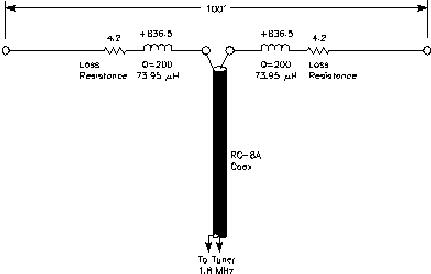
If a highly reactive antenna can be tuned to resonance, even without special efforts to make the resistive portion equal to the line’s characteristic impedance, the resulting SWR is often low enough to minimize additional line loss due to SWR. For example, the multiband dipole in Table 19.3 has an antenna impedance of 4.5 - j1673 ohm at 1.8 MHz. Assume that the antenna reactance is tuned out with a network consisting of two symmetrical inductors whose reactance is +836.5 ohm each, with a Q of 200. The inductors are made up of 73.95 mH coils in series with inherent loss resistors of 836.5/200 = 4.2 ohm. The total series resistance is thus 4.5 + 2 ´ (4.2) = 12.9 ohm, and the antenna reactance and inductor reactance cancel out. See Fig 19.6.
If this tuned system is fed with 50-ohm coaxial cable, the SWR is 50/12.9 = 3.88:1, and the loss in 100 ft of RG-8A cable would be 0.47 dB. The radiation efficiency is 4.5/12.9 = 34.9%. Expressed another way, there is 4.57 dB of loss. Adding the 0.47 dB of loss in the line yields an overall system loss of 5.04 dB. Compare this to the loss of 17.1 dB if the RG-8A coax is used to feed the antenna directly, without any matching at the antenna. The use of a moderately high-Q resonator has yielded almost 12 dB of “gain” (that is, less loss) compared to the nonresonator case. The drawback of course if that the antenna is now resonated on only one frequency, but it certainly is a lot more efficient on that one frequency.
Fig 19.6 — The efficiency of the dipole in Table 19.3 can be improved at
1.8 MHz with a pair of inductors inserted symmetrically at the feedpoint. Each
inductor is assumed to have a Q of 200. By resonating the dipole in this fashion
the system efficiency, when fed with RG-8A coax, is almost 20 dB better than
using this same antenna without the resonator. The disadvantage is that the
formerly multiband antenna can only be used on a single band.