.jpg)
AM voice was the second mode used in Amateur Radio (after Morse code). AM techniques are the basis for several other modes, such as single-sideband voice and AFSK. This material was supplied by Jeff Bauer, WA1MBK.
AM is a mixing process. When RF and AF signals are combined in a standard AM modulator, four output signals are generated: the original RF signal (carrier), the original AF signal, and two sidebands, whose frequencies are the sum and difference of the original RF and AF signals, and whose amplitudes are proportional to that of the original AF signal. The sum component is called the upper sideband (USB). It is erect: A frequency increase of the modulating AF causes a frequency increase in the RF output. The difference component is called the lower sideband (LSB), which is inverted: A frequency increase in the modulating AF produces a decrease in the output frequency. The amplitude and frequency of the carrier are unchanged by the modulation process, and the original AF signal is rejected by the RF output network. The RF envelope (sum of sidebands and carrier), as viewed on an oscilloscope, has the shape of the modulating waveform.
Fig 12.1B shows the envelope of an RF signal that is 20% modulated by an AF sine wave. The envelope varies in amplitude because it is the vector sum of the carrier and the sidebands. A spectrum analyzer or selective receiver will show the carrier to be constant. The spectral photograph also shows that the bandwidth of an AM signal is twice the highest frequency component of the modulating wave.
An AM signal cannot be frequency multiplied without special processing because the phase/frequency relationship of the modulating-waveform components would be severely distorted. For this reason, once an AM signal has been generated, its frequency can be changed only by heterodyning.
All of the information in an AM signal is contained in the sidebands, but two-thirds of the RF power is in the carrier. If the carrier is suppressed in the transmitter and reinserted (in the proper phase) in the receiver, significant advantages accrue. When the reinserted carrier is strong compared to the incoming double-sideband signal (DSB), exalted carrier reception is achieved, and distortion from selective fading is reduced greatly. A refinement called synchronous detection uses a PLL to reject interference. Suppressing the carrier also eliminates the heterodyne interference common with adjacent AM signals. More important, eliminating the carrier increases overall transmitter efficiency. Transmitter power requirements are reduced by 66%, and the remaining 34% has a light duty cycle.
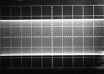
(A)
(B)
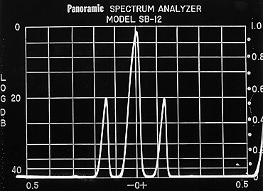
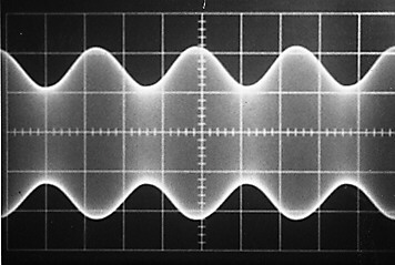
Fig 12.1 — Electronic displays of AM signals in the frequency and time domains. A shows an unmodulated carrier or single-tone SSB signal. B shows a full-carrier AM signal modulated 20% with a sine wave.
AM can happen at low levels (as in a driver or predriver stages of a
transmitter) or high levels, in the final output stage. The numbers are
consistent for both methods.
For example, to 100% modulate a 10 W RF carrier, 5 W of clean AF is required
from the modulator. Good engineering calls for a 25% overdesign; thus 6.25 W of
AF allows plenty of system headroom. The circuitry can then “loaf along” at
the 100% level.
Overmodulation occurs when more audio is impressed on a carrier than is
needed for 100% modulation. It is also known as flattopping. Overmodulation
causes distortion of the information conveyed and produces splatter (spurious
emissions) on adjacent frequencies. Splatter interferes with others sharing our
already-crowded bands: Prevent overmodulation at all times.
Years ago amateurs used ingenious ways to detect and prevent or control
overmodulation. Nowadays with solid-state, large-scale integration (LSI) chips
and microprocessor control, bullet-proof overmodulation prevention can be
designed into transmitters. The most familiar method is called ALC, for
automatic level control.
Although modern use of full-carrier AM on the amateur bands is very limited, there is a core group of AM aficionados experimenting with pulse duration modulation (PDM). This system was pioneered in AM broadcast transmitters.
This form of high-level modulation differs from conventional AM in that the
PDM modulator operates in switching mode, with audio information contained
during on-pulses. The audio amplitude is therefore determined by the duty cycle
of the modulator or switching tube. Those interested in further reading on the
topic should look in William Orr’s (W6SAI) Radio Handbook (published by Howard
W. Sams and Co) and the AM Press/Exchange (for contact information, see the
Address List in the References chapter).
The carrier can be suppressed or nearly eliminated by using a balanced
modulator or an extremely sharp filter. Contemporary amateur transmitters often
use both methods.
The basic principle of any balanced modulator is to introduce the carrier in
such a way that only the sidebands will appear in the output. The balanced-modulator
circuit chosen by a builder depends on constructional considerations, cost and
the active devices to be employed.
In any balanced-modulator circuit, there is (theoretically) no output when no
audio signal is applied. When audio is applied, the balance is upset, and one
branch conducts more than the other. Since any modulation process is the same as
“mixing,” sum and difference frequencies (sidebands) are generated. The
modulator is not balanced for the sidebands, and they appear in the output.