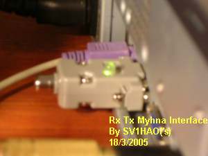
PTT Interface
A simple PTT Interface
Commercial external interfaces cost 100 Euro or more, depending on the additional futures. Due to the fact that most ham operators are on a limited budget, a homebrew approach is attractive. After examining various ways to interface the transceiver, it was found that the most practical way was using an Optocoupler via a COM port.
The gain of using an Optocoupler in this project is obvious. First of all, the total number of components is reduced, and the electric isolation between the transceiver and the computer is achieved. Last but not least, the total cost of the interface is less than 5 Euro --quite a difference compared to the prices of the commercial interfaces available. The voltage swing on these lines is -12v/-5v through +12v/+5v, so a Optocoupler can handle quite nicely the negotiation between the rig and the computer.
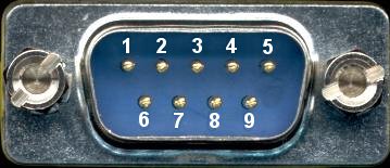
The interface is needed so the computer can send a request to the transmitter to transmit or receive. The most practical method is via a serial COM port using the RTS or DTR lines. Through these lines the PTT (Push to Talk) on the transmitter is activated. The analog audio is passed from the sound card directly to the audio in of the transceiver by simple cable connection.
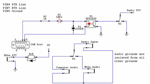
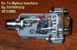
The circuit described below was made to connect the computer to the transmitter. It was designed as simple as possible to keep the number of components as low as possible.
As soon as the program activates the RTS line (or the DTR) the negative voltage
of the line turns to positive. This makes the Led D1 as well as the Led in the
Optocoupler U1 to light, making the emitter and the collector of the Optocoupler
to conduct, thus giving the ground needed to the transmitter to TX.
The Led D1 is not necessary for the circuit to work but it is a very useful visual indication of the status of the interface. An upgrade to this simple interface was to replace the Led with a dual polarity Led. This way, instead of having the led light up on TX, the led is green on Stand by (RX) and turns Red on TX.
In most cases the simple interface will be adequate for typical amateur use. In our case it is not enough. The reason is quite simple: Myhna uses standard prerecorded messages for typical transmissions. What happens if it is required to send information that is not included in the standard messages?