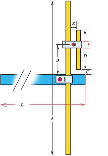
Dimensions of Dipole
A = 99 cm
B = see text
C = 24 mm
D = 26,5 cm
E = 14 mm
F = 12 mm
L = > 50 cm
 |
Dimensions of Dipole A = 99 cm B = see text C = 24 mm D = 26,5 cm E = 14 mm F = 12 mm L = > 50 cm |
Dipole and Gamma-match, they are both from the same material, like Alumunium tube (pipe) with an external diameter of about 8mm.
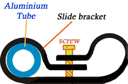
The "Slide" bracket has been constructed from an aluminium stripe, about 12 mm wide.
 |
 |
The "Gamma match" is made by a piece of Aluminium tube with overall length of about 26,5 cm (dimension D ). The space between Dipole and "Gamma" rod its about 22 mm (FIG. 3). Gamma rod is parallel to Dipole rod.
The "matching system" is made by stripping a part of RG58U cable, about 26 cm long. The most part of 26 cm must be insert into "Gamma" tube, just "insert" - do not connect anywhere. This way
we made a capacitor... as you know, a capacitor has two plates... here the first "plate" is the internal (stripped) cable of RG58 and the second "plate" its the Gamma-tube. (Actually, its a cylindrical and not a planar capacitor).
Note: because the internal diameter of Gamma-tube is larger from internal cable of RG58, you must insert again into central cable of RG58 the outer piece (cover), without the shield. This way, the central cable will be keeping in the center-point along Gamma - tube. Picture below shows how you prepare the RG58 cable in four steps.
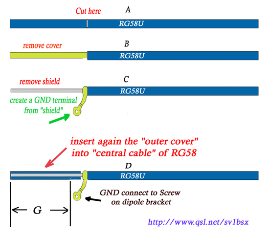 |
"G" part on picture above, will be inserting into "Gamma-tube". The "shield" of RG cable must be connect to the screw on the dipole center-bracket. Figure 5 below shows the details.
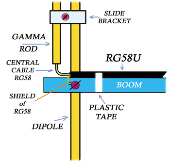 |
Now, I suppose you have already the dipole with "Gamma-match". Cut the RG58 cable in overall length between GND point (screw on dipole-bracket) and connector equal to "Lamda"/2 x 0,66 (0,66 = velocity factor of RG58).
For example: Using the formula
Wave length(Lamda) = 300 / F => L=300/145 => L=2.0689 meters
Lamda/2 for 145 MHZ = 2.0689 /2 = 1.034 meters...
Using Coaxial cables we have always a Velocity Factor. For RG-58 that is 0.66
So, a piece of Coaxial
cable equal to Lamda/2 is 1.034 x 0.66 = 0.682 m
That is the electrical length of Lamda/2 coaxial.
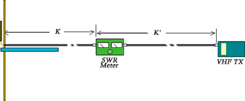
Thus, the total length from GND terminal on Dipole-bracket up to PL connector, is about 0.682 m or 1.365 m (x2) if the first is too short.(Dimension "K" on FIG.6). Just keep in mind that, use always Lamda/2 x 1,2,3 etc. in order to have enough length of Coaxial, between dipole and SWR bridge.
Put the connector into a SWR meter and connect the other side of SWR with an handheld VHF tranceiver. Keep in mind, the rest part of transmition line between SWR and VHF TX (dimension " K' "), which includes the SWR, it must be also resonable for the desire frequency , like "K" part.
Now, set the output power to "Low" on VHF and the frquency to 145.000 MHZ . By placing the dipole about 2 meters above ground, press the PTT and adjust the antenna by sliding (moving) the "Slide-bracket" up or down, looking simultaneously for the minimum SWR on the SWR bridge.
In my prototype antenna, the distance between Boom and "Slide-bracket" was 24 cm for SWR 1:1 (dimension "B" on FIG.1). Finally, secure the screw with a screw-driver on the Slide-bracket and don't forget: all screws they must be from bronze-material.
 |
Keep in mind: if you want just a simple dipole antenna (i.e for packet or APRS station), after the final installation in your tower the feed-cable it must be a good type of coaxial cable, like
RG213, H100 or similar... I've used just a piece of RG58 ( close to Gamma-match) because is flexible and that helps to make the Gamma, but unfortunately the RG58 has a very "High Loss" into 145 MHZ ... so, just make the final piece close to dipole with that and the rest meters with something much better ! (RG213, H100 etc)
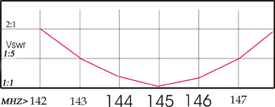
Finally, figure below shows the SWR curve between 142-148 MHZ. The dipole has an excellent SWR curve, absolutely symmetrical into 2 m Band.
 |