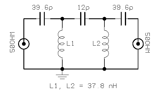
5th order High Pass VHF Filter
Sometimes many VHF-UHF modern tranceivers have problems
with BROADCAST Interference and CROSS-modulation
from FM commercial broadcast stations(88-108 MHZ Band).
FIG. 1 shows a simple Batteworth HI-Pass VHF Filter to reduse this problem .
FIG. 1
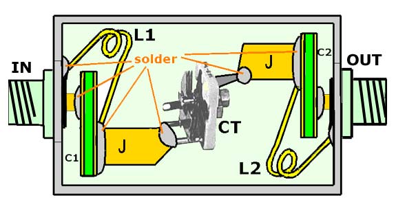
FIG.2 it is the mechanical construction in a small alumin diecast box.
Keep in mind, a filter above 100 MHZ sometimes is very difficult to construct without Insertion-Loss.Please, follow carefully the construction details
in FIG2 for the optimum results.
FIG. 2
C1 = C2 : it is a small parallelepiped piece of "Double-side epoxy PCB",
50 x 25 mm. This piece of Epoxy PCB is equal to a 40 pF capacitor and its a good, simple and cheap choice for this filter.
"J" is a copper jumper, to connect the CT with C1 & C2. It must be thick and wide enough, in order to be able to work as a conductor and not as an "inductor".
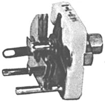
CT is a high-quality porcelain air-capacitor trimmer (FIG.3) and it is necessary for Hi-Power output tranceivers (> 5 - 50 W) because the RF current its extremely high throught CT capacitor. My experiments with any other type of capacitors was... smoke !
FIG.3: CT cap's trimmerAlternative, a combination of three Silver-mica capacitors 3.9pF/400V in parallel (totally abt 12 pF ) is enough for power up to 5 watts.
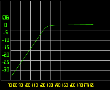
FIG.4 shows the "cut-off" responce of this filter
FIG. 4
The insertion-loss on 2 m. Band (144-146 MHz) was about 0.5 db with N-type connectors and 1- 1.2 db in UHF band.
Don't forget... the CT capacitor trimmer must be set to 12 pF.(if used)
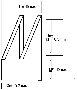
FIG.5 shows the construction details for L1-L2 ( 2 turns 0.7mm copper wire, 6.3 mm internal diameter, coil legnth 1 cm, legs-legnth 1,2 cm).
FIG. 5