If you need a cheap and easy to construct Subtone Generator for
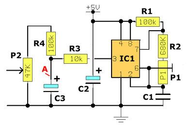
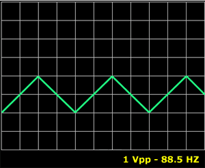
By using the R3, C3 and R4 we finally get a triangular waveform across P2 of about 1 Vp-p max (FIG.3). With this signal you can feed the SubTone (sub-audible) input-point of your VHF Rig, which is usually on the "mini socket" for the Optional subtone PCB. The necessary voltage is also there (+ 5V stab.)
Don't use any other type of capacitor (like ceramic) - the frequency drifting is 100% sure ! The output level is adjusted with P2. It's very important to use only enough output of Subtone generator, in order to
trigger-on a repeater, by adjusting the P2 . Much higher output will modulate your signal
high enough and this would be heard P1 is a multiturn pot. in order to adjust the output frequency.( It must be a good quality pot, ie Beckman). With a digital frequency meter between pin 3 and GND adjust P1 for the desire freq. ie 88,5 Hz.
I've modified my old FT-23 with this circuit... actually the last years in my country the VHF repeaters don't accept 1750 Hz "tone-burst" any longer, but they need subtone 88.5 Hz for triggering (like American versions). The price of the optional PCB CTCSS circuit was too expensive for an old rig, like my FT23 (about 40 % of the price that costs an FT-23 nowadays!)
So, just with 3 $, which is the total cost of the circuit, well done ! I've access to any SV repeater on my area without problem !!!!
EU-model VHF-UHF rig, here is a solution that works
very well.
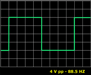
IC1 (FIG.1) as an unstable multivibrator giving a square wave output of about 4 V p-p ( 5Vcc) at pin 3 that has almost 50%
duty cycle (FIG.2).


For the best temperature stability, it's absolutely essential to be used a polyester capacitor for C1.
MKT - type is a second choice.
The bipolar type NE555 needs few mA, but the CMOS type like 7555 - LMC555 - TA7555, needs only 150 uA
(micro Amperes) and works fine with only 3 Volts, like a self-contained Lithium battery.
as 88.5 HZ "HUMmmmmm" on other receivers.
|
|
Makis SV1BSX(Febr.'97)