California Amplifier 31732 Downconverter
Retuning Modification

CalAmp
31732 designed to receive
terrestrial television broadcasts in the Multipoint Microwave Distribution
Service (or MMDS). The downconverter has
enough gain and local oscillator stability to serve as a Down Converter
for AO-40, by retunning the input BPF. Modification is easy or complex,
depending upon owner's shack. If a wideband multimode receiver is available,
like IC-706 or a scanner, there is no need to perform any modification more
complex than the Built-in BandPass
filter (BPF).
If only a 144MHz multimode receiver is
available, then is necessary to change the crystal, in addition to retuning the
BP filter.
BLOCK of 31732
The
block diagram is shown in figure below:
|
|
FIG.1
The
PLL including four stages: PLL chip, reference Xtal oscillator, VCO
operating over the appropriate range and a Prescaler to divide down the VCO
output for comparison in the PLL IC with the reference frequency. The phase
locked output of the VCO in the converter is normally 2278MHz. The whole PLL
system divides this by a total of 256 to compare with the reference crystal.
Therefore, to change the PLL frequency, we change the reference crystal and the
IF output.
Unmodified
the unit does not have enough sensitivity to receive signals from AO40 downlink
on 2401 MHZ. That is possible by
retuning the filter to work at 2400
MHz. Further work is required but provides superior results to that obtained by
the use of teflon shim/tape, like the WC0Y method.
|
|
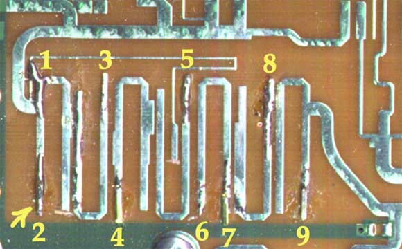
FIG.2
Fig.2 above shows the “modified” BPF from my 31732 (points 1-9). Using small pieces of copper or brass shim
0.001 or similar, it is possible to move the filter right into 2401 MHZ and
obtain best performance. These are individually tinned, and waved over the
existing stripline until an improvement can be obtained, whereupon they are
soldered in place, repeating the whole excercise until no further improvement
can be obtained. Many tabs and a fair amount of time and skill is required to
obtain the best results. Working ones way from the output side of the filter to
that of the input is the method to adopt when retuning this filter.
|
|
Fig.3
shows the “Bench setup”. You need a good quality “Signal Generator” (i.e
HP) and probably an additional ATTenuator between Generator and 31732. Keep in
mind, during retuning, the sensitivity of 31732 spectacularly increasing and
sometimes the “built-in” ATTenuator is not enough. The 31732 following by a
usual “DC insertion” unit, for Voltage feeding. A small Power Supply (PS) 18V /
0.5 A is enough.
After the DC insrtion Unit is the Receiver
with a SINAD meter connected into AF output.
Note
that it is very important to not manually tune this filter for the highest S
meter reading, the mixing process produces not only the wanted signal, but an
image signal (which will be noise). Tuning for best S meter reading will allow more of the unwanted 'noise' to
interfere with the wanted signal. Tuning the downconverter for best quieting
and signal/noise (or SINAD) will improve matters considerably. Access to a
SINAD meter is not so important if you have good ears, and can tell the
difference in quieting. An oscilloscope connected to the receiver's output will
aid manual retuning to some extent by examining the roughness of the modulation.
If only a 144-146 MHz SSB receiver is available, the local oscillator will need changing to
2256MHz (for satellite reception Xtal = 8.8125 MHZ). Thus, we have:
2401
- 2256 = 145 MHZ (IF)
Local
Oscillator Frequency
Crystal is in an HC49/u holder, 33pF load capacity fundamental, accuracy
is 10ppm over -30 to +60 Celsius.
The
received IF will then be available at 144MHz. Once the crystal is changed, the
operating frequency can be easily adjusted with a frequency counter by means of
the trimmer adjacent to the crystal. Remembering that if measuring the
frequency of the crystal oscillator, any error in trimming will be multiplied
by 256 at the Local Oscillator frequency.