for SSB - CW operation.
I have constructed a Homemade VHF Transverter from 28 MHZ to 144 MHZ, but the output Power its only 0,5 Watts, too low for this band, though a QRP-er.
I was looking for a Linear Amplifier to Increase the Output Power up to 5 Watts for QRP operation, but nothing was found.
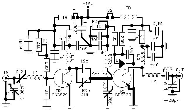
I designed the follow PA (FIG.1) with components of my "junk-box" and the result was excellent! Two cheap RF transistors, 2N3924 as driver and a BFS22A for final stage, giving an unexpected Output Power of 7-8 Watts maximum ! Actually, the first transistor has a gain of 6DB and the second abt 8DB, which that means a total amplification of 14Db, in others words we expected an output power about 10 watts, but in practice we have a serious limitation, because the BFS22 has a maximum output power of about 4 Watts ! ! !(Philips RF Power Bipolar - Data HandBook, page 65).
Anyway, if you put a large Hotsink into the case of BFS22, you can get easily an output power of 6-8 Watts, usually without over-heating problems for an SSB or CW operation, but never - I repeat never, for continuous "Key-Down" or FM operation !
 |
The input (50 Ohms) "matching" with TR1 base through two var. trimmers CT1 & CT2 and L1(3 Turns, 0,8mm Wire, Int Diam 6mm., L= 5mm). The L1 is 6-7mm above PCB. The TR1 has a simple Bias Circuit for Linear Operation and the variable resistor P1 needs to be "set" for an IDLE current of about 4-5 mA by removing the jumper "J1"(Computer type Jumper). Put a mA-meter between J1 terminals and set the P1 for 4-5 mA. After the adjustment, don't forget to put the J1-jumper again !
RFL is a choke of 6 turns 0.7mm wire, diam.- 6mm & L=10mm.
The output of TR1 is "matching" with the next stage via CT3 trimer and a 12pF capacitor in parallel, following by a "strip" 40 mm x 2.5 mm. Tap for CT4 at 15mm from TR2 base.
The TR2 has a more sophisticate Bias circuit than TR1. Actually, "D" diode is "temperature-tracked" and must be contact with "body" of BFS22. Some "heat transfer compound" like a Silicon-paste is necessary here. This diode (1N4148) regulates the Bias, depending on body-temperature of TR2.
The base of TR2 has a coil like VK200. The RFL in the collector of TR2 is similar to TR1. The Output Coil "L2" is made of 3 turns - 1mm Wire, internal diam.= 10mm, L=7mm. The coil is 5mm above PCB surface.
Finally, the Bias-current of TR2 must be adjusted, by following the same method of TR1 but in this stage you must removes the J2. Then adjust the P2 for an IDLE-current of about 25-30 mA and put again the J2.
Keep in mind, the TR2 its a small transistor . You must put two "asterisk-hotsinks" together(1st asterisk OVER 2nd asterisk and fixed together with a screw) for a safety operation, otherwise the BFS22 maybe will be destroyed. (The TR1 needs just a small hotsink).
All resistors are 0,25 W and the Capacitors 63V (ceramics). FB its a medium ferrite-bead, with 2-3 turns of VCC wire.
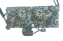
With this circuit I had QSOs from SV1 area to SV7 & SV9 (about 300 Km or more) several times, just by using a simple 3 Elements Homebrew Yagi Antenna (abt 6 DB Gain). All the reports was talking for excellent Linearity and I received also several compliments for my modulation. Actually I'm not a Fan of VHF-DXing (I love more the HF DXing), but the circuits was an unexpected surprise for me, about the Output Power. The total cost of it its a few $ and its very easy to construct, if you have experiance on VHF circuits. I've no any PCB here, my prototype created on a "double-side" PCB (13x5 Cm) using a gouge to make the "tracks" (believe me ! !). The other (lower) side being fully metallized to serve as "earth".

The project designed and made during 1993... actually, is still working !
Good Luck.
Makis SV1BSX
