 |
|
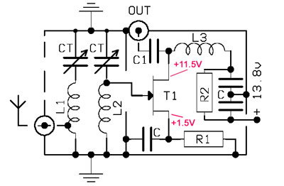
| T1= BF245 C= 10nF/63V cer. C1= 2n2/63V cer. R1,2= 270 /0.25W CTs= 50-120pF Pushed-Mica | * L1, L2: 4.5 turns, D=25mm length= about 15mm (air-coils) * L1: ANT-tap at 1.5 turn from GND * Both coils with 1mm wire L3= 100uH coil |
I designed a simple circuit having in mind my... junkbox!
So there is nothing unusual on this pre amp, all components are possibly available into Homenrewer's Shack.
The "heart" of unit it's a FET BF245. You need your solder-iron, a few additional components, and about 2-3 hours delightful work.
Ah, yes... I forgot it: Total Cost = 0 - 5 $ ! (depending upon your junkbox).
The input-section has a Band Pass Filter (BPF) with L1,L2 & CTs. These 2 parallel tuned circuits are resonated into 10 m Band. L1, L2 coils are close enough between each other, in order to achieve the necessary RF-coupling of BandPassFilter.
I have used two parallel tuned circuits in order to be able to cover the whole bandwidth of 10m Band (28-29.7 MHz) and on the other hand having in my mind a few... very "noisy" neighbours on lower edge of Amateur Band (see "CB band" !). Thus, my BPF filter rejects high enough any undesirable signal, which came on 10m Band from 27 MHz neighbour CB Band, as the Downlink of AO-7 is just 2 MHz above CB.
The FET (T1) is auto-biased by using the R1 resistor between Source and Ground, so the Gate is directly connected to "hot" point of L2. The drain has as load a small coil (L3 = 100uH). A few capacitors are necessary for decoupling. That's all !
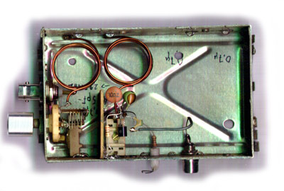
The circuit gives a Gain of about 20 dB, without problems. I made it into a small metallic box from an old TV-tuner by using the "Ugly-construction" method. Fast & easy. However, keep in mind to separate enough the input from output, in order to prevent any unwanted feedback. Take care at this point because ...."Mr. Murphy" always watching you ! If the preampl occurs feedback, then you have not made a pre-amp but a... "nice", noisy & damned... oscillator !
 |
 |
After construction, don't forget to tune carefully the two CT trimmers (Input BPF). The best-point is not the maximum amplification but close to this point, in order to be able to achieve best S/N. By choosing a very weak signal try to tune both CT trimmers, several times - again & again. You must looking for the best listening in the receiving signal with as low as possible Noise-Level, and on the other hand by keeping a good amplification factor. Then, your new homebrew preamplifier is ready for use.
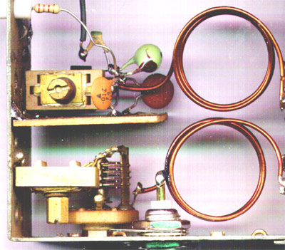
As you can see on my photos, I have added a small Johnson Trimmer (2-10pF) with external knob in parallel with first CT, in order to be able to tune (fine-tuning) between 28-30 MHz (band edges). It is not necessary at all, don't put it, the help which offers is very small.
Finally, the Picture below shows a simple but effective antenna for AO-7/Mode-A reception. I found randomly that, it has superior receiving than any other simple antenna (vertical, dipole etc) I have used. In practice I use this antenna for 30m Band (10.1 MHz), in order to be active on this frequency because my basic HF antenna system does not cover the 30m. In practice it's something like between Ground-Plane & Sloper antenna, so I named "GP-Sloper" !
Well, the story is that: one day I surprised when switched-ON this antenna (by accident!) on my receiver for AO-7 / Mode-A. The Downlink-signal on 29.450 was much stronger than anything else I have used ! After several observations it was obvious that this antenna can hear the AO-7/A stronger than my any other simple antenna I've tested for AO-7 Satellite! In practice, this GP-Sloper is about 3 x "Quarter Waves" on 10m, so probably has some additional Gain compared with a simple Quarter-Wave whip (or dipole). The bigger surprise for me is that, the Downlink-signal remains strong enough even the Satellite comes from back-side of GP-Sloper (antipode) ! Just when the Sat rising above the Horizon (AOS), and upto 10-15° elevation my 3 El. HF Yagi is quite stronger, but that is logical. Definitely the GP-Sloper has much higher radiation angle, but on the other hand it's a very simple construction for AO-7/A reception.
So, the picture below shows this "great stuff" ! It's very easy to construct it, just a few meters of wire, several ceramic-insulators and nylon string for supporting. The "L" is about 7.35m and the radials have about the same length.
Good Luck!
 |
That's all folks - Have Fun