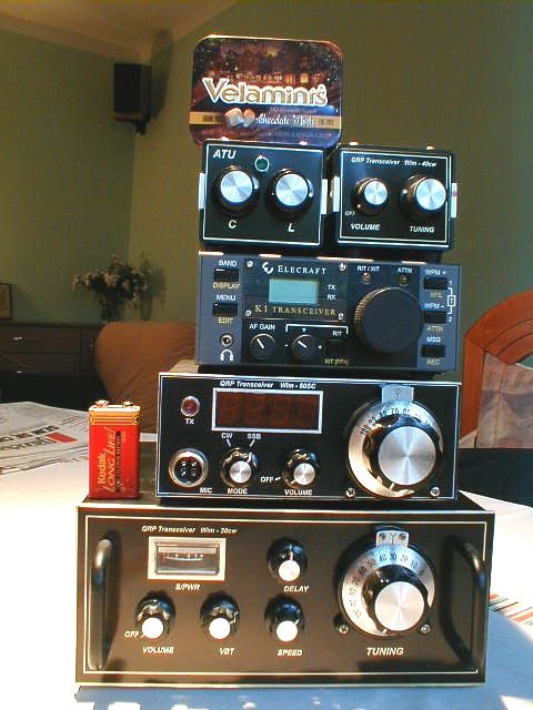
My QRP projects gallery ( obviously under construction )
See " tower of QRP power" first.....
First serious QRP rig I have built in 1995 just after reaching # 310 DXCC to prove myself that I have not forgotten soldering. This 14 MHz CW trx represents single superheterodyne receiver with 9 MHz IF and approximately 2W output transmitter. All "printed circuit" boards were designed by myself, and schematic is combination from many sources with my developments. Receiver is based on popular Plessey® ICs. Transmitter is based on keyed 9MHz crystal oscillator, so the signal is very clean. ( Do you remember 599X reports? ).
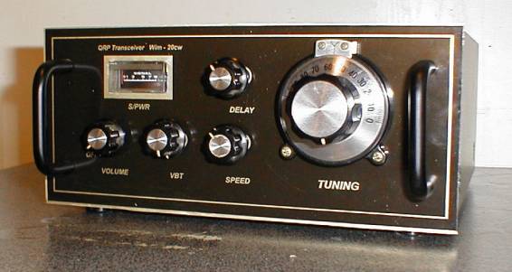
"Wim - 20 CW" - My first complete homebrew QRP rig
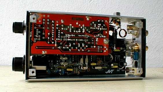
Second QRP trx has been built five years later by completing domestic company QRP kit . Originally this rig should work on 20m and 80m bands both CW and SSB, but I decided to assembly 80metre section only. Diagram is rather copy of "VK's TCF project" with some original modifications. Unfortunately some of those mods resulted non-working TX, so I had to re-design driver and PA stages to achieve at least 1,5 Watts output. I started this job on Christmas 1999 but finished just before summer holidays. "Wim 80 SC" still needs some improvement in VFO section.
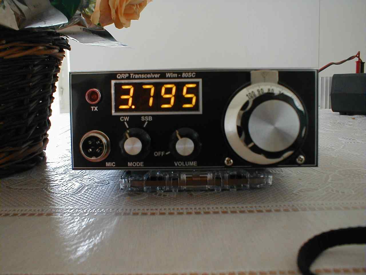
Front view of "Wim - 80 SC"
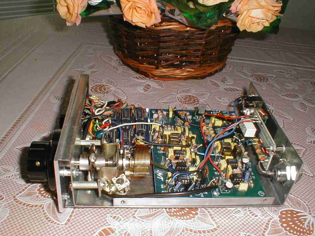
Inside view of "Wim 80SC"
Third rig I have just finished in March 2001. This is the smallest and the most lovely trx I have in my small collection.Direct conversion receiver and almost one Watt out enables satisfactory CW contacts on 40 meters. More details, including schematic you can find under "Forty - oner" button.
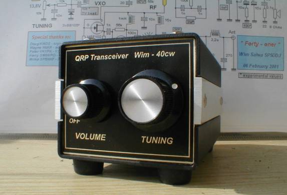
"Wim - 40 CW" ( "Forty - Oner" ) - My favourite......except K-1
For all QRP rigs presented above front and rear panels have been prepared and chemically printed by my Best Ham Friend - Ted VK3UX
Fourth rig is being developed. As usual I make a prototype board, tune parameters and finally assembly. TRX is expected to be finished before holidays. This is to be a 30M CW transceiver with 6MHz ladder filter optimised for CW and approximately 1W of output power. Below you can see what was done so far.
Wim - 30 CW ( as on 2nd of April 2001 )
But the Friday 13th of April I have changed my mind....
This will be an "Wim - 15 CW" transceiver, because I discovered that 30m band doesn't matches my contest's desire. By searching through crystals I have found a pair of 15,125 MHz which ideally work in tuned VXO (see "Forty - Oner " idea). IF was previously designed to be 6 MHz so the only problem was to re-calculate all L/C circuits including front-end band pass filter. Just one day before Easter, RX section started to sound. On Easter Monday morning I finally tuned VXO to the range of 14998 kHz - 15075 kHz ( stability was O.K. after short warm-up ) and played some hour with 4 pole ladder filter and BFO. I didn't know what bandwidth I achieved, but relying on my experienced hearing this had to be no worse than approx. 1 kHz wide. The only "instruments" I have in my shack are digital multimeter, TS-940 and RF probe.
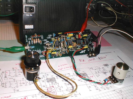
"Wim - 15 CW" working RX as on 16th of April 2001
Printed circuit board is made by local kit manufacturer (discontinued as a kit, all boards were on closeout sale ) and cost me 1$ only without components.
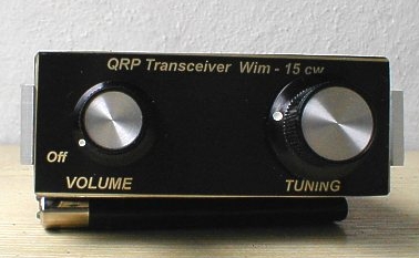
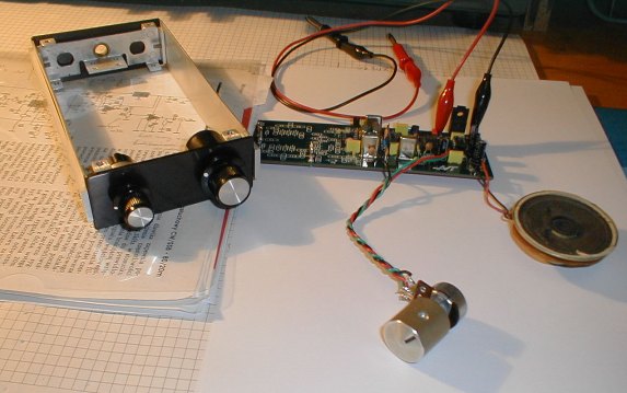
"Wim - 15 CW" finished but without case
"Wim - 15 CW" inside view
Hot comments:
"Wim - 15CW" became alive on 09.06.2001. First contact I made with G5VQ on 21042 kHz receiving RST449 but Eric copied everything, even WX report. Things to do: case painting, cleaning soldering points and field test with mini ATU and full wave wire.
What do I do next?
Next projects are already completed and described on separate pages.