Why using a cavity filter?
This began one evening when one of my ham-neighbours was very active, (SM7XEN hi). I think the aurora-conditions where good and since this ham-neighbour, at that time, only operated in SSB-mode, I then thought that it would be nice if I where able to sort out the CW-part of the 2m-band.
I got my hands on a cavity-filter originally used for mono-FM broadcasting. This filter is about 95cm high and the diameter is 17cm.
The filter is only made for indoor use and the outdoor preamplifier must still be able to handle the strong signals from the ham-neighbour. (One would probably not dare to put one of these in a tower anyway...)
How the filter works
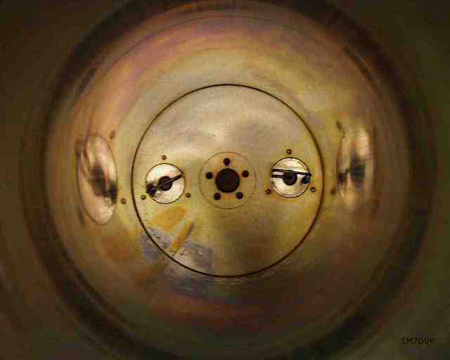
The cavity filter is made of four basic parts; cavity, inner-conductor, input- and output-loop, see schematic figure. You can see the inside of the cavity with the coupling-loops here.
Since the filter is originally made for about 100MHz, the wavelength is too long and the filter must be shortened. The input- and output-coupling loops must also be adjusted, ie shortened.
It is not necessary to shorten the cavity, ie the outer-conductor, only the inner-conductor! (Nice to know if you are about to build a diplexer for a FM-repeater!)
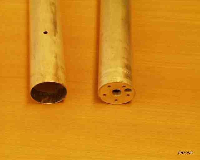
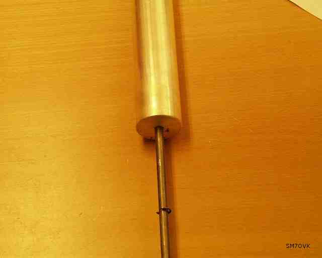
The inner-conductor is made of two tubes. The upper tube is firmly mounted with five screws on the cavity-top. The lower tube is fastened in a piston. The piston goes inside the upper tube and up throughout the cavity-top.
These two tubes are interconnected with a contact-tongue. By moving the inner tube up and down the filter frequency changes, "shorter" inner-conductor will give a higher center-frequency.
Modifications
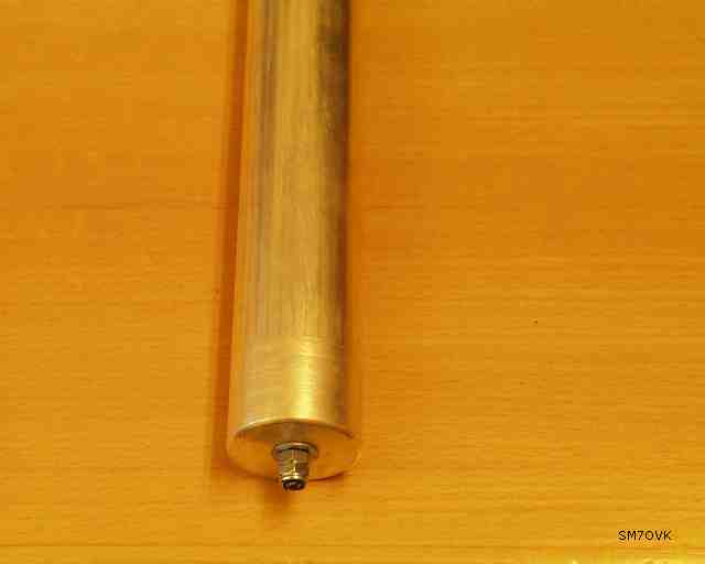
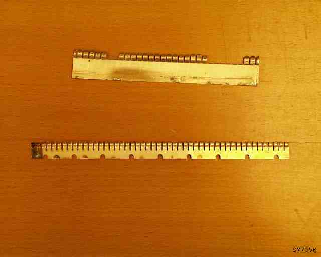
The inner-tube, in my filter, is made of brass and silvered. The first modification is to shorten the tubes and solder a new contact-tongue.
Contact-tongues are mounted under high pressure, often to high. This usually result in shorter lifetime and most often the tongues fall off. You see this clearly in this photo.
I found a new contact-tongue and soldered it with a hot-air-gun. It's important to have a lot of heat, but with this hot-air-gun it really is quite simple. The biggest problem was to get the right length of the tongue and keep it in place during soldering.
When the filter is demounted one should also clean every contact-surface since several pieces are made of aluminium and aluminium-oxide will not lead current. At some points on the filter it is VERY important to have a good ground-connection, especially on the cavity-bottom. If not the Q-value will be lower and this lowers the filter-performance.
All components are DC-grounded, and one must therefore take care if one would like to feed a preamplifier through the coaxial-cable and put the bias-T on the antenna-side of the filter!
Result
The result is a very narrow filter with nearly 100kHz of usable bandwidth, ie nearly too narrow! The dip is VERY DEEP but also very sensitive to mechanical shock and temperature changes!
It is also important to use good coaxial-cables. I think one must use double-shielded cables for this application, since a bad cable would ruin the filter-performance by leak through the cable-shield.
Further tests
When a nearby ham-club where participating in a CW-contest I thought that I maybe should test with two filters, one for the CW-part and one for the SSB-part. I therefore made an arrangement with two filters and two transfer-relays, see figure. With these two relays it's possible to switch the filters in/out.
This is "over-kill"! It was fun to test but it is also too much work having two filters that can be detuned by mechanical chock or temperature changes. For me it was not worth the maintenance of the filter-system.
As a tip, do not place the cavity on a table. Use a separate shelf fastened on a wall. Put the cavity on a thick rubber disk to minimize the risk for mechanical shock.
Today I only use one filter for the CW-part. I think that there will be several filters available since more and more broadcasting stations totally abandon mono-transmissions and therefore need larger bandwidth. I hope that this page gives some hints about necessarily modifications of this type of filter. (Most single cavity-filters I have seen are constructed in this way.)
The filters could also, with very good results, be used for FM-repeaters.
"Next step"
The next step could be to use one filter for filtering and the other as a notch-filter. In this way it would be possible to notch out a nearby station during a longer contest! I will get back to this when I have it running. This will be a further modification of the filter since the frequency adjustment must be changeable fast and easy. As often, the biggest problem is to find a reliable solution usable year after year...