This page describes a DC to DC voltage converter, pretty simple, for currents up to 500 mA. The circuit is
possible to increase the Output Current upto 1 A, by using some special components, like Shotcky Diodes, good Toroid coil etc. The efficiency is pretty good, rising to 95% !
The circuit have been designed in order to feed
my 2.4GHZ DownConverter for portable operation ( DownLink AO40 satellite), which it needs at least 16 Volts (nom.16-24V) Voltage input. This was
not possible with my 12 V / 6Ah Sealed Lead-Acid Battery. Some operators they removed the internal 12V Voltage Regulator (7812) from DownConverters (D/C), in order to supplying directly the D/C with 13.8 V. It's an acceptable combination for others but I don't agree with it.
On the other hand, I've a long-long coaxial cable from Shack to my roof (35 m. ) and I do not know which percentage of voltage it will reach above, into my D/C with 13 DC Volts source and 35 m. long of coaxial cable. Anyway, the unit has been designed primary for my portable DownLink. On the Shack it's easy to get 18-24 Volts from a small Power Pack. Probably my circuit is very useful for
several other uses, like the voltage feeding of a 24 Volts small RF Linear, for camping, solar panels, boats etc.
Actually, the components that I have used are very common and cheap! The complete unit
it has a cost of 5 Euros ($) or less !
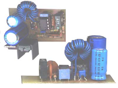
FIG.1Fig.1 above shows the
unit, in the PCB and FIG.2 the electrobic diagram. The basic circuit is taken
from FAIRCHILD Data Sheet, which describe this IC family, like UC3842, 43, 44,
45 ICs. They are Low Startup Frequencycurrent-mode PWM controllers, designed for
Off-Line and DC to DC converter applications with minimum external components.
These ICs feature a trimmed oscillator for precise Duty-cycle control, a
temperature compensated reference, high gain error amplifier, current sensing
comparator and a high current totempole output for driving a Power MOSFET, which
it can operate within 100% duty cycle.
FIG.2
BTW my CalAmp 31732 D/C needs just 2-3 hundreds mA, so my circuit has been not constructed with special
components. The maximum current on my unit is upto 500mA, with good regulating on output Voltage.
I have used simple silicon fast diodes like BA159 (1Amp.) as D1 & D2. We can to replacing D1-diode with several types Fast silicon diodes, like BY297, BY299 etc. without problem. This type of diodes they is very common,
they used on most models of color TV. But if you want a Higher current output, see my NOTES below.
FIG.3 shows the components layout, into PCB. The unit is pretty small (5 x 2.8 cm).
FIG.3
D1 & R6 are soldered in vertical position. I have used just a "jumper" from Source lead of T1 to R3. All components
are shown on the Figure above. The PCB has been designed in order to have a small surface.
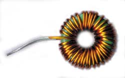
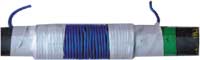
Few words about "L" toroid: I don't know how you can find a similar toroid, like that I have used. I don't know the "AL"of my core, it was from my Junk-Box. It's a Green toroid core 18x7mm, with 38 turns of 0,7mm wire. (Actually I have an Inductance meter on my bench and is pretty easy for me to measure any coil).
For this reason, I checked my circuit with several Coils from my Junk-box. Well, there is not too critical the
value of this coil. But, with correct (100uH) value we have the maximum efficiency and this is enviable.
FIG.4 shows the Toroid which I've used with excellent efficiency. In the Right picture is an alternative coil,
on a usual ferrite road from MW radios (with Yellow "Dot"). I had equally good results with 38 turns (0.5 mm wire) and my Inductance-meter it showed that his value they is equal to 100uH (like my toroid coil). So if you
can't find a toroid, try it with a ferrite rod ! In practice it's much-much bigger, but it works fine.
FIG.4 On any case, If you have an Unknown coil, just put it on and try it. ! The following table shows the maximum Output Voltage,
depending upon "L" value. You can increase or decrease the turns into your toroid, till the best results.
By using a resistor 100Ohm/15 W on the Output as LOAD, try with P1 to adjust the Output Voltage. If you have maximum output lower than 20-24 Volts, the coil is wrong. With a correct coil the output voltage should be 29-35 Volts. Then you can trimmed the P1 for the desire output voltage, ie 24 V.
This is my suggestion. Keep in mind, for Low currents it's necessary a wire or a cable not too wide (0.5mm is enough).
| |
Max Volt-Output vs L inductance
|
I (Ampere) under test
(100 Ohm Load) |
4mH |
300 uH |
200 uH |
100 uH |
50 uH |
| +- 0,25 A |
<21 V |
<24 V |
<20 V |
30 V or Higher |
<19
V |
|
|
|
|
|
|
|
|
|
|
|
|
| Part-list |
- T1 = BUZ11
- L= 100uH Toroid
- IC1= UC3843
- C1= 1000uF/16V
- C2,4= 0.1 uF/63V multilayer
- C3= 2n2/63V MKT
- C5=470pF/63V ceramic
- C6= 100pF/ ""
- C7= 2200uF/35V (see NOTES)
|
- D1 = BY159 (see NOTES)
- D2 = BY159
- R1,6,7= 10K
- R2= 22Ohm
- R3= 1K
- R4= 150K
- R5= 0.27Ohm
- R8= 12K
- P1=2K2 Trim
|
| All Resistors are 0,25 Watts |
NOTE: * For Higher Current output a Shotcky diode RPG30 or better is necessary as D1.
* C7 must be
105� type, for switching power supplies.
* R5 must be decreasing to 50% of value or lower (0.12 Ohms).
* T1 and D1 needs probably HotSinks for safe operation.
*
Additionally, the "L" toroid is very important for good efficiency.See my measurements on Table above with various values of L. The best results have been achieved with 100uH toroid-coil. So, if you
want High Current, you must be very careful with L value and the wire of inductance... 1mm wire is wide enough for this current. Finally keep in mind, the inductance depending upon frequency on circuit and my measurements was measured with R1=10K and C3=2n2 (operation period = 11uS)

Have Fun
Makis SV1BSX (May 2003)
| All rights reserved 2003-2004 |
| For HAM-Radio PERSONAL USE ONLY |
 |