Various "Signal Source" circuits using rare XTALs, blocks etc. as fundamental oscillators to generate through a Fast silicon diode the necessary multiply frequency for 2,4 GHZ. My idea is simple: a VHF is the most
basic equipment into a Ham-shack. Just by using a handheld VHF as signal source, we can easily get an output
signal arround 2,4 GHZ. For example, by multiplying the 144MHZ x 16 the final F= 2.304 MHZ (13cm).
The AO-40 freq. is 2,4 GHZ, that means 150 x 16 = 2400 MHZ.
|
FIG.1 shows the electronic diagram of my 2.4 GHZ signal source. R1 & R2 are 100 Ohms resistors in parallel. The two resistors acts as a 50 Ohm "Dummy Load" to terminate the VHF RF-output. Keep in mind, this Dummy is for Low Power use, depend on resistors power.
The 144-150 MHZ signal driving the 1N4148 diode through CT & L1. The resonance frequency depend on CT capacity.
ATTENTION: DO NOT USE the VHF with "HI" Power output ! In this case, the Dummy-load (R1, R2) & the Diode probably will be destroyed !
ADJUSTMENTS
1) Connect the RF-out of a handheld
VHF into Signal-source input.
2) Set the output to "LOW". An output power of about 500 mW (0.5 W) is ideal.
3)Remove the A-B short-link and replace with a 0-100 mA - meter.
4)Press the PTT on VHF. A deflection must be indicate into mA-meter. Adjust the CT to peak the diode current (at approximately 30 mA). On my Signal-source I've got a value of about 35 mA with 500mW RF Output of my handheld VHF.
5) Remove the mA-meter and replace it with the A-B "short-Link" permanently.
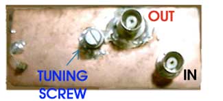
After that, if you have your Mode-S DownConverter in working order, press the PTT and adjust the "Tuning-screw" for maximum output... that's all !
 |
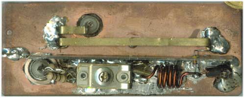
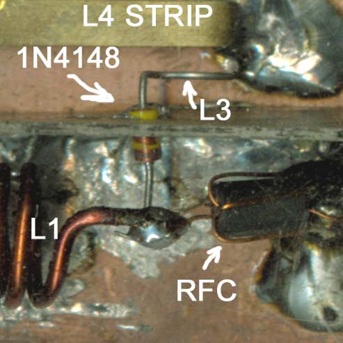
FIG.2 shows the practical construction of my 2.4 GHZ source. The unit is built on a double-side epoxy PCB which forms the lid of a standard die-cast box (3.6 x 1.5 x 1.2 in) like the most units of this type.
Below they are some fotos from my Web camera to take a view of contruction.
   |
PART LIST
Input - Output = BNC Female chassis connectors
R1, R2 = 100 Ohms carbon resistor, 1-2 W
CT = Push-mica trimmer 10-60 pF
C = 1nF Feedtrough Capacitor
C2 = Tuning-screw (Diam = 3.5mm)
L1 = 5 turns, int. diam 6mm, length = 10mm, wire = 1mm
L2 = RFC (4 turns 0.2 - 0.3mm wire on a small ferrite-bead)
D1 = 1N4148
L3 = 10mm of Diode's warped-leg, 5mm above GND surface, parallel to L4, spacing L3-L4 = 3mm
L4 = 55 mm of bronze-strip, 3mm wide, 5 mm above GND surface
L5 = 10mm length parallel to L4, 5mm above GND, spacing L4-L5 = 3mm.
NOTES
* A Shield between Input-section (R1,2 CT, L1, L2, C) and L3-L4-L5 is necessary
* 1N4148 diode passes through a small hole drilled to the shield
*The "Tuning-Screw's" hole must be drilled exactly on the CENTER of L4 - space.
*The "Nut" of tuning-screw is soldered on the "Outer" side of Box (NOT between L4 and Ground).
![]()
Have Fun
Makis SV1BSX (July 2002)
![]()