 |
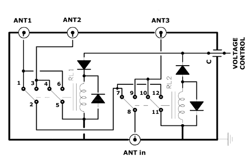
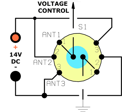
The FIG.1 shows the Antenna-Box (on the roof) and the FIG.2 the control Box (shack).
The Antenna-box contains 2 relays. RL1 is activated by apllying positive voltage to it, where as RL2 needs negative voltage, depending on diode polarity.
In other words, if the control-wire is connected to possitive (+V) respecting to GND the RL1 is "on" and RL2 "off".
If the wire-control is connected to negative (-V) the RL1 is "off" and the RL2 "on".
The GND (second cable) is
the outer cable (shield) of RG-cable.
Table below shows the relation between S1-RL1-RL2 & ANT 1, 2, 3
| Voltage CONTROL | RL1 | RL2 | ANT-input to: | ||
| OFF | OFF | & 7-8 (RL2) |
|||
| ON | OFF | & 7-8 (RL2) |
|||
| OFF | ON |
 |
The Control-Box (FIG.2) includes just a rotary switch 2x3. Please, keep in mind: its absolutely necessary an independent Power-Supply for this Antenna-box. A small Power-pack (self plug-in)12-14 Volts / 200mA its enough.
DO NOT USE the same Power Supply with your other transceivers !!! (If the S1 switch turn-on to ANT3 we have
"Short-circuit" between possitive and ground of PS ! That will be destroyed immediately the S1.)
RL1-RL2 are 12V relays and all diodes are 1N4004. C its a feedtrough capacitor (1nF) but if you havn't a feedtrough - don't worry about, it is not critical. Replace C by 2-3 ceramic cap's 1nF/63V in parallel.
My Antenna-Box has been costructed on a diecast alumin's box. I've used four female-chassis PL259 connectors for ANT-input & ANT 1, 2 ,3 output terminals.
The Control Box on my shack (including S1 rotary switch) is a small plastic box.
Finally, the wire connections between the contacts of RL1-RL2 have been designed in order to "Ground" the unused antennas. In other words, if the ANT1 is connected to the ANT-input (S1 to ANT1), ANT 2 & ANT 3 are connected to "Ground". If the ANT2 is connected to ANT-input (S1 to ANT2), ANT 1 & ANT 3 are "Grounded" etc.
That's all folks !
Have fun !