Space communication has forced the use of Circular polarization. The fundamental advantage of circular polarization is that all reflections change the direction of polarization, precluding the usual addition or
subtraction of main and reflected signals. Therefore there is far less fading and flutter when circular polarization is used at each end of the link. The use of circular polarization at one end only gives a loss of about -3dB.
In order to achieve the full advantages of circular polarization it is necessary for all stations to use it. The table below shows the relationship between Horizontal, Vertical, RHCP (Right Hand Circular Polarization) & LHCP
(Left Hand Circular Polarization). The RHCP is also known as CW (ClockWise) Polarization and LHCP as CCW (Counter ClockWise) Polarization.

The following pictures shows the Vertical, Horizontal and Circular polarization.
| Vertical polarization |
 |
| Horizontal polarization |
 |
Left Hand Circular Polarization
(LHCP) |
 |
Right Hand Circular Polarization
(RHCP) |
 |
 A usual question among Radio-Amateur operators is : how is possible to achieve Circular polarization?
 In practice, the Amateur Satellite operators using two basic methods:
Helical antennas and crossed-Yagis antennas.Helical antennas offer easily the wanted circular polarization, depending on how is constructed. In practice its a large air-coil onto a boom, so
ClockWise (CW) winding gives RHCP and vice-versa, but sometimes that is a disadvantage as its impossible to invert the
polarity. If the Helical antenna is CW gives RHCP. The CCW Helical gives LHCP.
 |
Typical Helical antenna:
as you can see, on this Helical the winding is CW (ClockWise).
Thus, this antenna generate RHCP. |
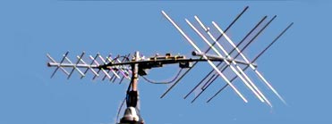
This page will describe mainly the cross-Yagi method. Reporting the term "Cross-Yagis", we mean for example two identical Yagi-antennas which are the first one in Vertical position and the second in Horizontal position. In any case the angle between these two antennas must be always 90�, so its also possible to put these antennas on "X" arrangement, the first one with
angle of 45� and the second with angle 135� vis-a-vis to "CrossBoom". The picture below shows a typical "X" arrangement with VHF & UHF "cross-Yagi antennas in order to cover the LEO Satellites.
The "X" arrangement has a small advantage for a simple reason: the metallic CrossBoom does not affect in the antenna's efficiency in contrast with V-H arrangement (V-H = Vertical-Horizontal), where the CrossBoom is between Horizontal-antenna's elements. That is unwanted ! Figure below shows what happens under this condition: on left Horizontal antenna the element is shadowed by CrossBoom.
But, if the CrossBoom is made from non metallic material (wood, PVC etc), in this case there is not any significant effect between CrossBoom and Horizontal-antenna, so is possible to put the two antennas with Vertical and Horizontal placement.
On the other hand, the V-H arrangement offer a small advantage in case you need to have a "switchable" antenna system, in order to change polarization between Vertical (for mobiles), Horizontal (DXing) and Circular polarization (Satellites). Under this placement, the V-H arrangement needs the minimal number of coaxial Relays, in order to be able to make this system "switchable" between Vertical-Horizontal-RHCP polarizations, in contrast with "X" arrangement which needs much more Coaxial-relays (and phase-stubs).
OK, now how is possible to connect these two crossed Yagi antennas? in parallel?
Well, Yes and ... No ! The method with "Crossed-Yagis" need two basic requirements in order to generate Circular polarization:
a) we need to "match" these 2 antennas
b) we need a "phase delay" in order to generate Circular polarity (details below).
Analyzing the case "a", its obvious that If we have two antennas which are
connected between each-other, we need a better way than the connection just
in parallel.
The reason is simple: if two antennas of 50 Ohms connected in
parallel, the Impedance on connection point is 50/2=25 Ohms. That is a
problem, as you have a mismatch with Coaxial cable, Transmitter etc. Under
this condition the SWR is 2:1.
Still the goal is to connect the two antennas
in parallel so the joint impedance matches with the coax cable from the RX/TX
in the shack. As the coax cable is 50 Ohms we need 50 Ohms as well on the
connection point of the two antennas.
That means each antenna should be 100
Ohms because then the impedance on the connection point will be 100/2 = 50
Ohms.
For this reason we use "matching stubs" between the antennas and
Coaxial cable.
What is the "matching Stub" ?
The "matching Stub" is a piece of Coaxial cable with appropriated calculation in impedance (Z), overall length etc., which acts as a kind of "Impedance transformer" between 2 known but unequal impedances (Z1, Z2).
Due to "Quarter Wave" formula, is possible to calculate the intermediate "Z" of a "Quarter Wave" ( ) coaxial piece, in order to be able to match 2 different impedances.
Quarter Wave formula = 
A mere example: I have an antenna
with Z=50 and I need as a termination-point an impedance of 100 Ohm.
Is it possible?
Yes, by using a "Quarter-Wave" coaxial cable with different (intermediate) Z, in order to "match" the Antenna's Z (50 Ohm) to a wanted "termination" Z (100 Ohms).
In this case we have:
Z = Unknown Z
|
Z1 = Antenna Z
|
| Z2 = Termination Z |
Z1 & Z2 are known. Antenna's Z = 50, Termination Z = 100 Ohms.... so the formula will be:
Z= Z1 * Z2 =>
Z=50 * 100 =>
Z=5000 =>
Z= 70.7 Ohms
Z1 * Z2 =>
Z=50 * 100 =>
Z=5000 =>
Z= 70.7 OhmsVoila ! the new impedance is 70.7 Ohms
OK, we found a new Z=70.7 Ohms... but what to do now with that new "Z" ?
As we said before, by using a "Quarter Wave" piece () of coaxial cable with this Z-value (70.7 Ohms), is possible to match the 50 Ohms antenna to a
termination of 100 ohms. But its very important to keep in mind, here we talking for "Electrical Quarter Wave".
"Electrical Quarter Wave" ( ) means, a Quarter Wave coaxial piece reduced in length by the Velocity Factor (VF) of Coaxial cable due to reduced propagation-speed of electrical current into Coaxial cable vis-a-vis to propagation-speed on "free space". The VF of each one Coaxial cable is known from the related tables of manufactures. For example, the VF of RG213, RG11 is 0.66.
OK, now how is possible to calculate the whole necessary Coaxial's piece in order to match the 50 Ohms with the 100 Ohms?
The method in order to solve this problem is:
1) we choose the type of Coaxial. Impedance of 70.7 Ohms in Coaxial cable does not exist. The closer impedance of Coaxial cables is 75 Ohms, like RG11, RG59 etc. In practice the "mismatch" between 70.7 and 75 Ohms is very small, so the RG11 is perfect for this job. Supposed that we choose the RG11, the VF = 0.66.
2) We need to know the Wavelength ( ) in operation frequency. The formula is
  , where f is the operation frequency in MHZ. For example, in 2m Band the middle-point of Satellite subzone (145.8 - 146.0 MHz) is 145.9 MHZ, so the formula is:
= 300 / 145.9 = 2.056 m
3) Now we divide the by 4, in order to have the :
= 2.056 / 4 => = 0.514 m (or 51.4 cm)
4) Now we know the length of "Quarter Wave" () for 145 MHz.
So the Electrical "Quarter Wave" () is:
* VF
The VF for RG-11 is also known (0.66), so the = 0.514 * 0.66 =>
= 0.339 m
CONCLUSION: between 2 different impedances of 50 & 100 Ohms is enough a piece of "Electrical Quarter Wave"
() of 75 Ohms (designated as "Matching-Stub"), in order to "match" these two unequal impedances (see following picture).

OK fine, we learned how to match a 50 Ohms impedance to a 100 Ohms impedance. But how is possible to connect two 50 Ohms Yagis with 50 Ohms Coaxial? still wondering..
The connection with 2 Yagi-antennas following the above mentioned with a slightly different approach:
each antenna is connected to a common-point by using a piece of "Electrical Quarter Wave" () Coaxial cable of 75 Ohms (Matching Stub), in order to transform each 50 Ohms antenna up to 100 Ohms and the two are placed in parallel to produce 50 Ohm again.
The following picture shows this combination. On left picture, the "up" & "down" points on the edges of each 75 Ohms Coaxial piece connected to 50 Ohms antennas. At the opposite edge of each Coaxial we have 100 Ohms impedance. If these 100 Ohms impedance-points connected in parallel, the new
impedance is 50 Ohms (100 / 2 = 50), so at this point the joint impedance matches with the usual 50 Ohms Coaxial cables (like RG213, H100, AirCom etc) up to the Shack.
That's all !
Keep in mind, the same approach is used also for the "stacked" Yagi-antennas, Collinear dipoles etc. The "Matching Stub" is a common method in order to match 2 (or more) identical on impedance antennas. So, at this point there is nothing unusual with "Crossed-Yagis". They are just two identical Yagi antennas connected between each other in order to have the optimum "matching". The only difference on Crossed Yagis is that, they are not both in Horizontal or Vertical polarization like stacked-Yagis, but the first one is in Horizontal and the second in Vertical polarization.
Closing the "Matching Stubs" chapter, the picture below shows few details
onto coaxial piece's preparing, in order to be able to function as correct "Matching Stub" ().

 ...about Phase delay
The second requirement in order to generate Circular Polarization (except "Matching" ) from two Crossed-Antennas is a very interesting and sometimes difficult case. We talking for the "Phase Delay".
As mentioned on previous chapter, the Satellite Amateur Radio communication Service basically uses RHCP (Right Hand Circular Polarization) and sometimes LHCP (Left Hand Circular Polarization). But, even the world's top telecommunications engineers got this one wrong on the first transatlantic TV braodcast via Telstar satellite !
Firstly, before anything else in order to understand right the relationship between Linear, Circular and Elliptical polarization, is necessary few words about the theory... so:
|
Theoretically, linear and circular polarization are special cases of
elliptical
polarization.
Consider 2 electrical vectors at right angles to each other.
The frequencies are the same, but the magnitudes and phase angles can vary.
If either one or the other of magnitudes is zero, under this condition the
polarization
is LINEAR.
If the magnitudes are the same and the phase angle between the 2 vectors
(in timebase) is exactly 90 degrees, under this condition we have CIRCULAR
polarization. Any other combination between these two limits gives ELLIPTICAL
polarization.
|
From this theory, if we talking for Circular polarity is obvious that,
its easier to achieve.... Elliptical polarization, than the wanted Circular
!
Is high enough just... a small fault (incorrectly "phase stamp", bad "matching stub"
etc)
as the Circular polarization happens only when the two electrical vectors
have 90� difference in phase, all the rest cases give Elliptical and Linear
polarization!
Thus is clear enough , in order to be able to generate in a crossed-Yagis antenna system Circular poalarization, we need to
insert into the first (or second) antenna a "Phase Delay" equal to 90�.
How is possible to insert this necessary "90� phase delay" into 2 crossed-Yagis?
In practice this can be done by using two methods:
| 1) Electrical method |
| 2) Physical method |
Analyzing the "Electrical method", I will not extend in complicated and sometimes difficult theory about "Phasing". With simple words is well known that a piece of Coaxial cable appears a "Delay" in Phase equal to 90� (recognised here as "Phasing Stub").
The following picture shows clear enough what happens in the above mentioned circuit which has been used in order to connect two identical Yagi-antennas.
As you can see on picture above, in practice this system includes the arrangement that has been described in the previous chapter about "Matching Stubs". In addition, is shown the necessary "Phasing Stub" in series with ANT-2 that has been added. Thus, the feeding of this antenna is "delayed" in phase by 90�, in order to be able to generate the wanted Circular polarization. That's all !
OK but what impedance should be this "Phasing Stub"? 75 or 50 Ohms?
Definitely 50 Ohms ! This piece of Coaxial working as "90� Phase delay - stub", not as "Matcing-Stub". So it must be equal in Ohms with Antenna's impedance. Don't forget that. Also the overall length of it is also "Electrical", that means * VF, so we talking also for "Electrical Quarter Wave" ().
The calculation at this point is similar to "Matching Stub" as above mentioned, so for the Satellite-Subzone (145.9 MHz) a " 90� Phase-Stub" in practice has overall length = 0.339 m. (or 33.9 cm). The basic difference from "Matching Stub" is that the Coaxial cable that used as "Phase-Stub" is 50 Ohms.
So, keep in mind that: we use 50 Ohms
for "90� Phasing Stubs", 75 Ohms for "Matching Stubs".
OK... now how is possible to control when the generate polarization from my crossed-Yagis is RHCP or LHCP?
Depending on the feeding between the two dipoles onto each cross-Yagi antennas. The following picture shows clear enough how is possible to generate RHCP or LHCP ( rear view of dipoles).
The "+" shows the connection of central-cable of each Coaxial. The "0" point ondicates the direct feeding of Vertical Dipole (ANT.1) and the "1" indicates the "delayed" feeding of Horizontal Dipole (ie through a "phase-stub" in ANT.2).
Its obvious that, in practice is high enough just the simple changing of Coaxial's center-conductor feeding between left or right half part of Horizontal dipole, in order to change the polarization between RHCP & LHCP.
Well, now I am really confused ! The left picture above shows the generation of RHCP, but due to "0" starting-point and continue to the the delayed-point "1", this circularness is definitely CCW ! Why RHCP polarization? Are you sure?
Good one observation ! Well, you have right but the antenna beaming just from the opposite side, the front side. So looking the left-picture Dipole from rear, the circularnes seems to be CCW. But if you turn your self on the front-side of antenna, the circularness is just the opposite (CW) ! Always the polarization is recognizable looking the "light source", "antenna" etc from the front side, the beaming-side. In other words the "antenna" and the "observer" are always "face to face". So the pictures above are both 100% correct.

The following is Greek fonts:
� ������ ������������� �� ����:
�� ���� ������ ������ ������������� �� ��� "����" ��� ����� �����.
�� � ���� ��� ������� ��������� ������ �������� ��� �������� �/4 (���� �������� ��� ������ ��� ����), ������������� �������������� ����, �� ����� ����������� ��� ������ ��� ������� ����� �����������.
�� � ���� �������� ��� ���� �/4 (���� �������� ��� ������ ��� ����), ������������� ����������� ����, ���
����������� ��� ������ ��� ������� � ������ ����� ��������������.
SV1BSX © Copyright
All rights reserved |
| For HAM-Radio PERSONAL USE ONLY |
 |
October 2005