FUNDAMENTALS OF
ELECTROMAGNETIC RADIATION
2.7 HALF-WAVE DIPOLE ANTENNAS
One of the simplest practical
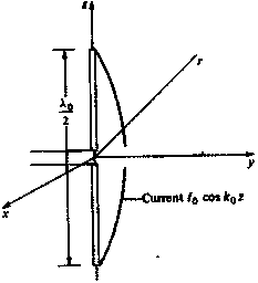
antennas is the half-wave dipole antenna shown in Fig. 2.10. It is
usually fed from a two-wire transmission line. Each arm of the antenna is
very nearly one-quarter wavelength long. It has been found both
theoretically and experimentally that the current distribution on a thin half-wave
dipole antenna is closely approximated by a sinusoidal standing wave of the
form
![]() � ���
� ���
![]()
The current is, of necessity,
zero at the ends where z= �
![]() . We can find the far-zone radiated field from the half-wave
dipole antenna by using Eq. (2.50), given in the previous section.
. We can find the far-zone radiated field from the half-wave
dipole antenna by using Eq. (2.50), given in the previous section.
 �
�

Figure 2.10 The half-wave
dipole antenna.
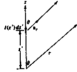
With reference to Fig. 2.10,
it is seen that the unit vector
![]() ,
,
![]() , and
, and
![]() . Hence Eq. (2.50) gives
. Hence Eq. (2.50) gives

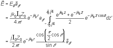
We now note that
![]() , so
, so
![]() . Thus we find that
. Thus we find that

The magnetic field is given
by Eq. (2.49b) and is

The power flux per unit area
is given by

The total radiated power is
obtained by integrating this expression over the surface of a sphere of radius
r; thus

This integral can be
evaluated in terms of the cosine integral �
![]()
The values of
this integral are tabulated .� The result of carrying out the integration is
![]()
When we equate this
expression to ![]() , we find that the radiation resistance of the half-wave
dipole is 2x36.56, or 73.13
, we find that the radiation resistance of the half-wave
dipole is 2x36.56, or 73.13 ![]() . The transmission line that feeds the half-wave
dipole should have a characteristic impedance of 73.14
. The transmission line that feeds the half-wave
dipole should have a characteristic impedance of 73.14 ![]() for maximum power
transfer.
for maximum power
transfer.
The directivity function for
the half-wave dipole is obtained by using Eq. (2.55) multiplied by r` and
Eq. (2.57) in the defining relation (2.34) and is

The
maximum directivity is 1.64, which is only a modest increase over the value of
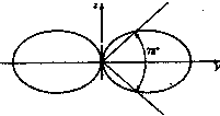
1.5 for the short current filament. The radiation pattern in the E
plane is shown in Fig. 2.11. The half-power beam width is 78�, which is
only a small amount less than the 90� for the short current filament. The most
important difference between the short electric dipole and the half-wave
dipole antenna is that the latter has a radiation resistance of 73.13
![]() �which is much larger
than the ohmic resistance would be for most practical antenna structures. Thus
the
�which is much larger
than the ohmic resistance would be for most practical antenna structures. Thus
the
 �
�
Figure 2.11 Principal E-plane radiation pattern
for a half-wavelength dipole antenna.
�
See J. A. Stratton, Electromagnetic Theory, McGraw-Hill
Book Company New York, 1941. Sec. 8.7.
�� E. Jahnke and F.
Emde. Tables of Functions, Dover�
PubIications, New York, 1945.
gain is also very nearly equal to 1.64. It also
turns out that when the dipole is a half-wavelength long (actually a few
percent less) the input reactance is zero, so the input impedance is
essentially equal to the radiation resistance.