
PS7PC - ACAUÃ 40

ACAUÃ 40, UM TRANSCEPTOR QRP PARA SSB E CW
Carlos, PS7PC
APRESENTAÇÃO
O projeto do transceptor teve como base o conhecido BITX, do colega Arshan Fahan, VU2ESE, que utiliza amplificadores bidirecionais, de configuração muito simples e eficiente. Mesclei as idéias de Farhan com algumas soluções que já havia utilizado em um projeto anterior, o BETA 2, e que me asseguraram um transceptor barato, eficiente e de excelente desempenho.
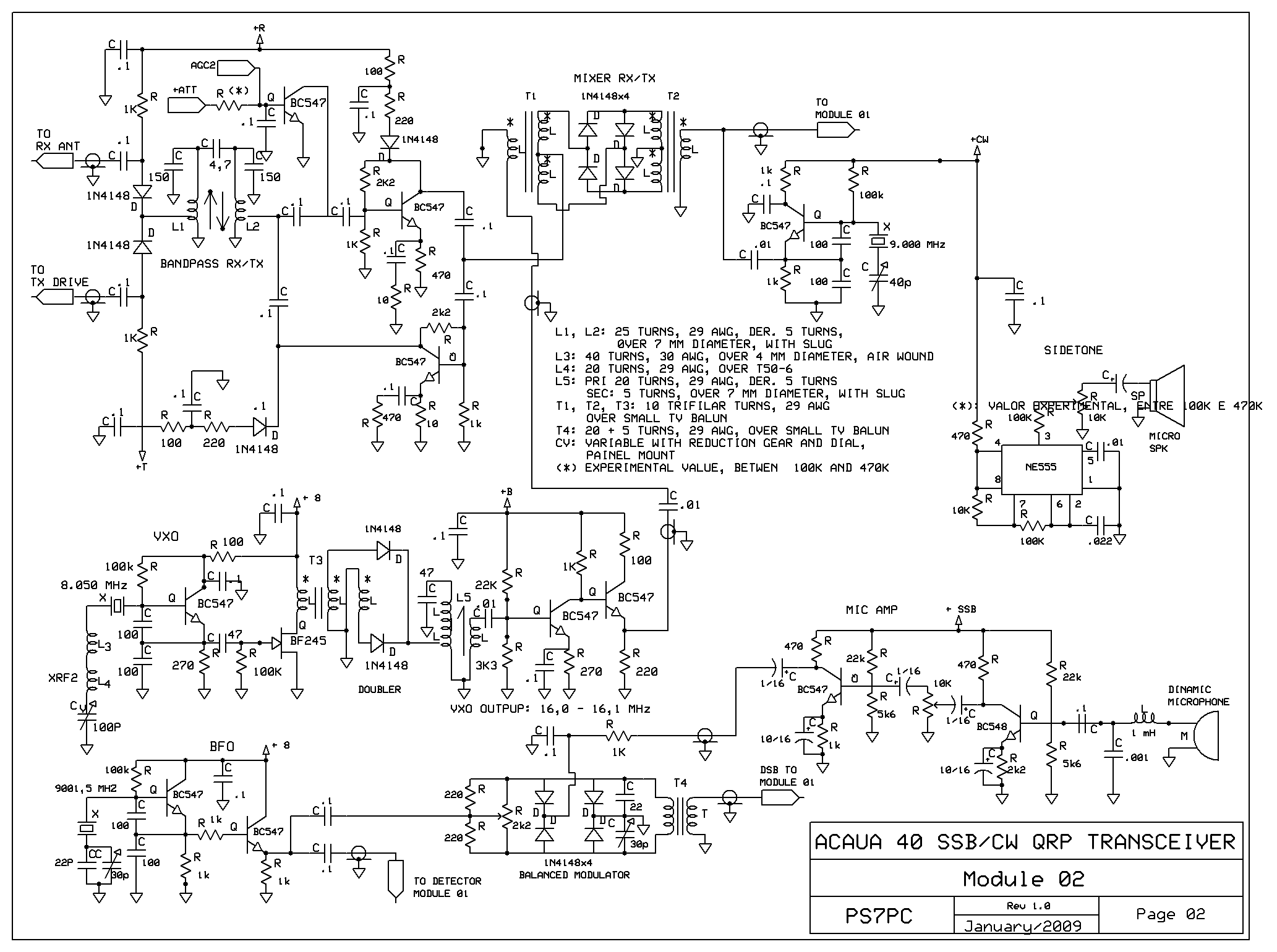
VXO
Optei por utilizar um oscilador variável a cristal, dada à excelente estabilidade desse tipo de oscilador, quando comparado aos OFV convencionais. A cobertura vai de 7040 a 7100 KHz, com variação de freqüência de apenas 100 Hz, após 10 minutos de aquecimento, ao longo de toda a faixa. Depois disso, o oscilador se mantém estável, conforme averigüei com um frequencímetro.
Utilizei um cristal de 8.050 MHz, do tipo HCU, em um oscilador Colpitts, com sintonia através de um circuito série, formado por dois indutores e um capacitor variável de 100 pf, em conjunto com um mecanismo de redução. Na sequencia, o sinal é dobrado e amplificado, num circuito formado por dois diodos e um indutor, copiado do projeto DM1, divulgado há anos pelo De Marco, PY2WM.
O VXO poderá ter uma cobertura de banda maior, chegando facilmente até o início da faixa, com a mesma estabilidade, o que possibilitará cobertura total do segmento de CW. Optei por uma cobertura menor porque o mecanismo redutor de que dispunha não me permitiu uma variação de freqüência mais “suave”. Além do mais, só faço minhas chamadas em CW na freqüência internacional destinada ao QRO, 7.040 KHz.
Outra opção – que não fiz - é utilizar mais de um cristal, para cobrir toda a faixa de 40 metros. Assim, com outros dois cristais, um de 8.100 KHz e outro de 8.150 KHz, pode-se cobrir a faixa em três segmentos de 100 khZ cada. Mas atenção: o chaveamento deve ser feito o mais próximo possível dos cristais, para evitar ligações longas. Use uma chave reversível rotativa com 3 posições para isso.
Aconselho a montagem desse tipo de oscilador variável a cristal, como uma excelente e simples forma de se obter estabilidade de freqüência, similar aos bons equipamentos comerciais modernos, que usam PLL´s e VCO´s, bem mais complexos. A estabilidade do equipamento, aliás, tem sido a característica mais destacada pelos colegas com quem tenho mantido QSO´s.
RECEPTOR
O receptor é de conversão simples, com FI de 9 MHz. O sinal é selecionado pelo relê de chaveamento, passa pelo filtro passabanda, comum à recepção e transmissão, e em seguida é amplificado por um simples BC547, de onde vai para um misturador passivo, duplamente balanceado, composto por T1, T2 e diodos associados, que também é comum à transmissão.
O filtro que utilizo é da marca alemã KOR, tem 2,4 KHz de banda passante, e foi obtido em uma sucata. Quem preferir, pode substituir o filtro comercial por um caseiro, normalmente composto por 4 cristais idênticos e capacitores associados, com variação máxima de uns 100 Hz, e capacitores associados. Um filtro desse tipo foi o utilizado pelo Farhan, em seu BITX. É evidente que um filtro comercial elimina os problemas de ajuste de banda passante.
O sinal, já em FI, é amplificado por outro BC547, passa pelo filtro à cristal de 9 MHz e é novamente amplificado por um MC1350P, oque assegura um ganho mínimo de 50 dB. O sinal é demodulado num detector de produto a diodos e o áudio resultante passa por um filtro passabaixo, é pré-amplificado por um BC547 e daí segue para o amplificador de potência, um CI LM386.
O volume obtido é mais que suficiente para alimentar um pequeno alto-falante de 3 polegadas, ou fones de baixa impedância, caso seja providenciado um plugue reversor no painel frontal.
AGC E ESSÍMETRO
Numa banda como a de 40 metros, saturada de estações locais, um bom sistema de controle automático de ganho é essencial. Optamos pelo uso de dois AGC´s distintos, ambos derivados de áudio. O primeiro controla o ganho do CI MC1350 e já é clássico na literatura, tendo sido divulgado por Louis Facen, PY2BX, há uns 30 anos.
O segundo AGC permite controlar o nível de sinal na base do transistor amplificador de RF, logo após o filtro passabanda, simplesmente levando o sinal à massa em níveis variados, através de um transistor BC547, que atua como uma resistência variável. Utilizo para isso um duplo operacional, o LM358. Um dos amplificadores alimenta o AGC, com tensão positiva obtida em dois diodos 1N4148. A outra metade do CI amplifica o sinal de áudio, que é retificado também por dois diodos, e alimenta o medidor de unidades “S”. Note que o medidor também é utilizado como medidor de potência em transmissão.
BFO
O BFO é formado por um oscilador Colpitts, com um transistor BC547. O cristal utilizado tem a frequência de 9.001,5 KHz e é do tipo HCU. O ajuste da banda passante é feito através de um trimmer miniatura de 40 pf, do tipo plástico. O sinal obtido é amplificado por outro BC547 e vai alimentar tanto o modulador balanceado em transmissão, quanto o detector de produto em recepção.
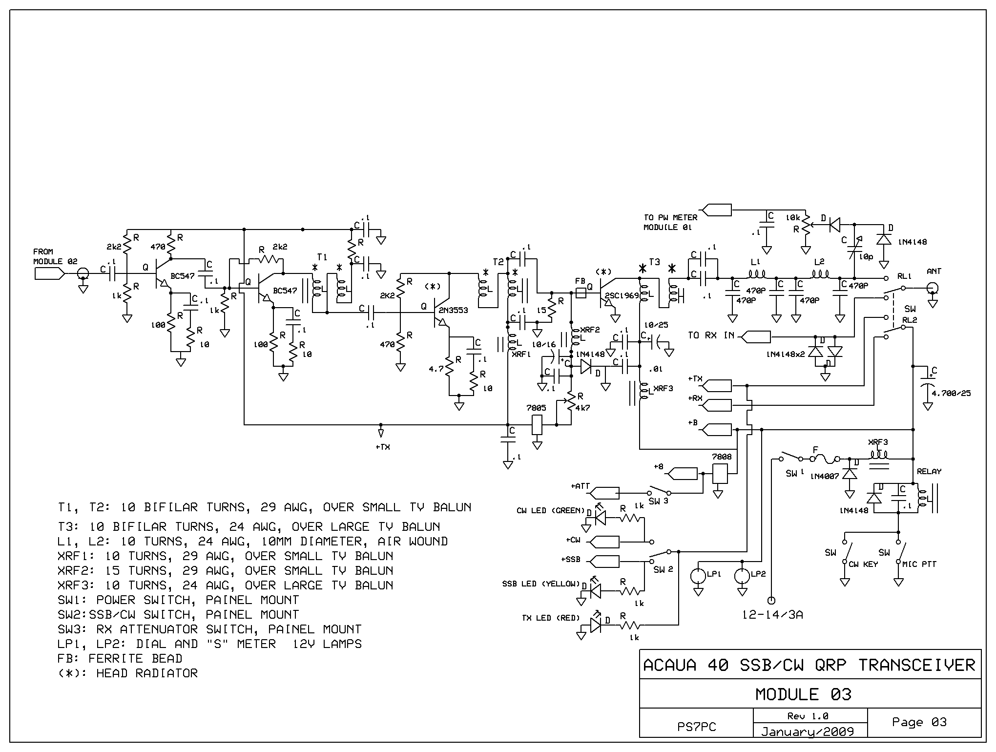
TRANSMISSOR
O sinal de voz é captado por um microfone dinâmico, de baixa impedância, pré-amplificado por um BC549, de baixo nível de ruído. O sinal passa por um potenciômetro de controle de ganho, afixado no painel, e é amplificado por um BC547, de onde segue para o modulador balanceado. Quem preferir, pode utilizar um microfone de eletreto na entrada desse módulo, com o que se poderá obter um maior ganho de modulação.
O modulador balanceado é do tipo clássico, com quatro diodos. A portadora, vinda do BFO, é eliminada através de ajustes no trimpot de 2k2 e no trimmer plástico de 30 p. O sinal DSB resultante é então encaminhado para a unidade de FI, formada por dois amplificadores idênticos, com transistores BC547. Note que entre o primeiro e o segundo amplificador está o filtro a cristal, comum à transmissão. A seleção de sinais de transmissão e recepção no filtro é feita mediante chaveamento por diodos 1N4148, em circuito também clássico. O próximo estágio é o misturador balanceado a diodos, também comum à recepção. Em seguida o sinal, já em 40 metros, é amplificado por um transistor BC547, passa pelo filtro passabanda e segue para o módulo de saída, composto por quatro estágios, em configuração banda larga, também clássica.
Após o estágio final de potência, composto por um transistor 2SC1969 e componentes associados, o sinal em fonia ou CW segue para a antena. Uma amostra do sinal de RF é retificada por dois diodos 1N4148 e a tensão positiva obtida vai alimentar o medidor, que pode ser calibrado em watts.
CW
A portadora de CW é gerada através de um oscilador Colpitts independente, que utiliza um cristal tipo HCU, na freqüência de 9.000 KHz. Esse sinal é injetado direto na entrada do misturador balanceado, fazendo um bypass en todos os circuitos utilizados para a geração de SSB. Note que o circuito amplificador de microfone fica sem alimentação quando se passa para a modalidade de CW. O sidetone necessário para a monitoração em telegrafia é gerado por um simples oscilador de áudio, com base num NE555.
Percebi que quando se ligava a saída do gerador de sidetone ao mesmo alto falante utilizado em recepção, havia distorção do áudio. Assim, optei por usar um segundo alto falante, exclusivo para a monitoração de CW, do tipo miniatura, de 8 ohms e 1 polegada de diâmetro, utilizado em alguns fones de ouvido. Ele foi colocado no painel traseiro do equipamento e a intensidade do sidetone pode ser regulada em um trimpot.
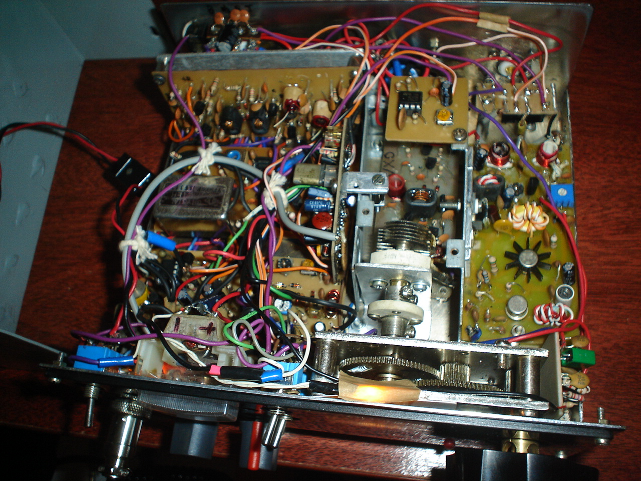
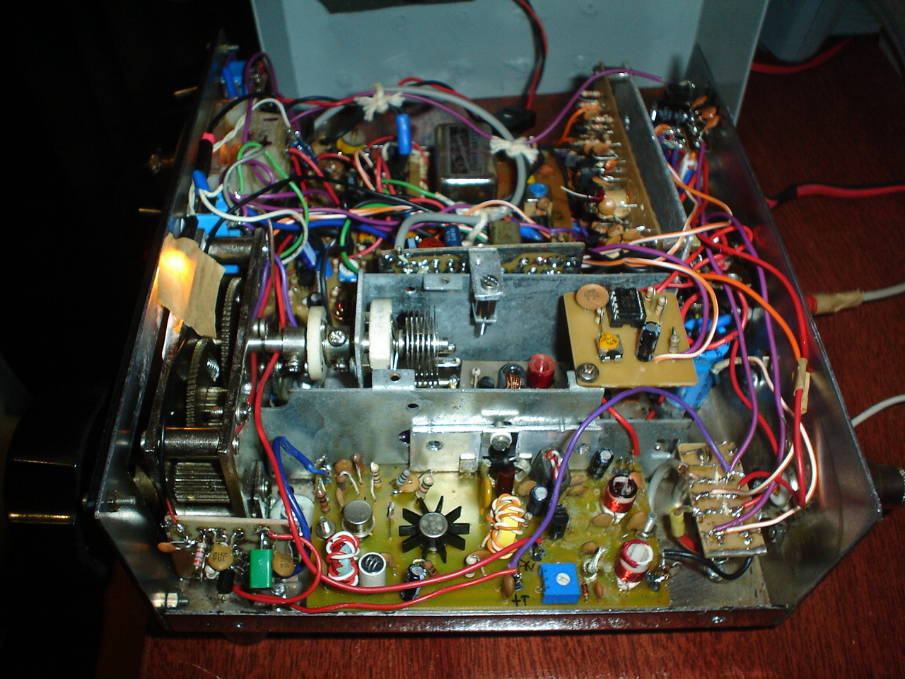
MONTAGEM
Utilizei placas de circuito impresso, feitas artesanalmente. Assim, não as posso disponibilizar, mas creio que elaborar as placas não será algo difícil para os bons montadores, com a experiência necessária para enfrentar desafios do porte de um transceptor de SSB deste tipo.
As placas foram dispostas dentro de uma caixa metálica medindo 6x21x18 centímetros, obtida numa sucata. O painel frontal foi realizado em uma placa de acrílico translúcido, com impressão invertida em silkscreen, que é afixado por 4 parafusos sobre a frente da caixa metálica.
Primeiro foram aplicadas as letras e marcações, também invertidas, em tinta branca, e depois feita uma demão de tinta spray preta fosca por cima. Dessa forma as letras ficam por dentro da placa de acrílico, o que impede que as marcações sejam riscadas com o uso ou desapareçam com o tempo.
Reservei um pequeno retângulo sem pintura na placa, que permite acessar visualmente o dial analógico utilizado. Este é impresso em papel branco numa impressora laser, e iluminado internamente com uma pequena lâmpada. Os dois leds indicadores de CW e SSB, do tipo retangular, foram montados na lateral do dial, por trás da placa frontal.
O uso da placa de acrílico
permite até que se possa polir o painel do rádio, sempre que se quiser, dando
excelente aparência ao equipamento.
DESEMPENHO
Uma das virtudes do ACAUÃ 40 é a excelente relação sinal-ruído obtida, graças ao uso de misturador passivo a diodos, como aliás tem sido comprovado e amplamente divulgado por outros colegas montadores. Para isso também contribui o sistema de amplificadores bidirecionais projetado pelo Farhan, que tem excelente desempenho. O receptor é sensível e bastante seletivo, mesmo dispondo de apenas uma única conversão. Também não notei a indesejável modulação cruzada, que ocorre quando uma estação potente opera em frequência próxima a que você está utilizando.
A transmissão tem sido bem reportada pelos colegas, depois que o equipamento foi ajustado para o melhor desempenho. A potência ideal obtida foi de 12 watts PEP, o que me permite participar rotineiramente de rodadas locais e regionais e trabalhar estações de DX, utilizando uma simples antena dipolo, quando a propagação está aberta.
Enfim, o ACAUÃ tem sido meu companheiro fiel no hobby escolhido, retribuindo galhardamente os muitos meses que dediquei à sua montagem e ajustes.
73´s
Carlos, PS7PC
Observação: Acauã é o nome de um pássaro, típico do Nordeste do Brasil, muito conhecido pelo seu forte canto.
ACAUÃ 40, A SSB AND CW QRP TRANSCEIVER FOR 40 METERS
Carlos, PS7PC
PRESENTATION
The design of
the transceiver was based on the known BITX, from Arshan Fahan, VU2ESE, which
uses bidirectional amplifiers, the setup very simple and efficient. I mix the
ideas of Farhan with some solutions that had already used in a previous project
for 20 meters, the BETA 2, and I secured a transceiver cheap, efficient and with
excellent performance.
VXO
I chose to use a variable crystal oscillator, given the excellent stability of
this type of oscillator, compared to conventional OFV. The coverage is from
7,040 to 7,100 kHz, with variation in frequency of only 100 Hz, after 10 minutes
of heating, all along the track. After that, the oscillator is stable, as
confirmed with a frequency meter.
I used a 8,050 MHz crystal, the type HCU, in a Colpitts oscillator with line
through a series circuit, formed by two inductors and a variable capacitor of
100 pf, together with a mechanism of reduction. In sequence, the signal is
doubled and amplified in a circuit formed by two diodes and an inductor, copied
from the project DM1, released years ago in Brazil by De March, PY2WM.
The VXO coverage may have a higher bandwidth, up easily to the top of the track,
with the same stability, which will cover the segment of the CW. I chose a less
coverage because the mechanism for reducing that I had not allowed a variation
frequency of more "soft". Moreover, just do my calls on CW in the
frequency for the international QRP, 7,040 KHz.
Another option - which I did not - is to use more than one crystal to cover the
entire range of 40 meters. So, with the other two crystals, one of 8,100 KHz and
8,150 KHz to another, you can cover the entirely band into three segments of 100
kHz each. But attention: the switching should be done as close as possible to
the crystals, to avoid lengthy connections. Use a key reversible rotating with 3
positions for that.
I advise the assembly of such a variable crystal oscillator, as an excellent and
simple way to achieve stability in frequency, similar to good commercial modern
equipment, which use PLL's and VCO's, with more complexity. The stability of the
equipment, moreover, has been the most prominent feature by colleagues with whom
I have kept QSO's.
RECEIVER
The receiver is
simple conversion, with if in the 9 MHz region. The signal is selected by
switching the relay, passing through the bandpass filter,
common to the reception and transmission, and then is amplified by a
simple BC547, which goes to a passive mixer, double balanced, composed of T1, T2
and associated diode, which is also common to the transmission.
The filter wich I have used was an German mark KOR, has 2.4 KHz of bandwidth,
and was obtained in a junk box. Those who prefer, you can replace the filter for
a home business, usually composed of 4 identical crystals and associated
capacitors, with maximum variation of about 100 Hz. One such filter was used by
Farhan in his BITX. Obviously, a commercial filter eliminates the problems of
adjustment of bandwidth.
The signal, already in IF, is amplified by another BC547, passes through the
filter of 9 MHz crystal and is amplified by a MC1350P again, what guarantees a
minimum gain of 50 dB. The signal IS demodulated in a product detector with
diodes, and audio from passing through a low pass filter, is pre-amplified by a
BC547 and then goes to the power amplifier, an IC LM386.
The volume obtained is more than enough to feed a small speaker, 3-inch or a
low-impedance headphones, if a plug is provided on the front panel.
AGC AND “S” METER
a good system of automatic gain control is essential in the
40 meters band, saturated by local stations. We opted for the use of two
separate AGC's, both derived from audio. The first controls the gain of IC
MC1350 and is already in classical literature, and was disclosed by Louis Facen,
PY2BX, 30 years ago.
The second AGC to control the signal level at the base of the RF amplifier
transistor, after the band pass filter, simply taking the signal to the mass at
various levels, through a BC547 transistor, which acts as a variable resistance.
I used for it a dual IC, the LM358.
One amplifier feeds the AGC amplifiers with voltage positive obtained in two
1N4148 diodes. The other half of the IC amplifies the audio signal, which is
also rectified by two diodes, and feeds the "S" meter units. Note that
the meter is also used as a gauge of power in transmission.
BFO
The BFO is formed by a Colpitts oscillator with a transistor BC547. The crystal
has used the frequency of 9,001.5 KHz and is the type HCU. The adjustment of the
bandwidth is done through a miniature 40 pf Trimmer, plastic type. The signal
obtained is amplified by another BC547 and will feed both the balanced modulator
in transmission, as the detector product in reception.
TRANSMITER
The voice signal
is captured by a dynamic microphone, low impedance, pre-amplified by a BC549, a
low noise level. The signal passes through a potentiometer to control the gain,
posicioned on the panel, and is amplified by a BC547, which follows to the
balanced modulator. You can also use a electret microphone to entry in this
module, with which you can get a higher gain of modulation.
The balanced modulator is a classic configuration, with four diodes. The carrier,
from the BFO, is eliminated through adjustments in trimpot of 2k2 and 30 pf
plastic trimmer. The DSB resulting signal is then forwarded to the unit of IF
formed by two identical amplifiers with transistors BC547. Note that, between
the first and second amplifier, is a crystal filter, common to the transmission.
The selection of
transmission and reception of signals in the filter is made by switching diodeS
1N4148, circuit also classic. The next stage is the balanced diode mixer, also
common to the reception. Then the signal, now at 40 meters, is amplified by a
transistor BC547, passes through the band pass filter and goes to the output
module, composed of four stages in setting broadband amplifiers.
After the final stage of power, comprising a transistor 2SC1969 and associated
components, the signal in voice or CW follows to the antenna. A sample of the RF
signal is rectified by two diodes 1N4148, and obtained positive voltage will
feed the meter, which can be calibrated in watts.
CW MODE
The CW mode is generated by an independent Colpitts oscillator, which uses a
crystal type HCU, the frequency of 9,000 KHz. This signal is injected directly
into the balanced mixer, making a bypass in all the circuits used for the
generation of SSB. Note that the microphone amplifier circuit is off when it
goes into the CW mode. The sidetone need for monitoring in telegraphy is
generated by a simple audio oscillator, based on a NE555.
I noticed that when connecting the output of the generator to the same speaker
used in reception, there was distortion of the audio. So, I chose to use a high
second speaker, exclusively for the CW monitoring, the kind miniature of 8 ohms
and 1” in diameter, used in some headphones. He was placed on the rear panel
of the equipment and the intensity of the sidetone can be regulated in a trimpot.
MOUNTING
I used the circuit board, made craftsmen. So I can not offer a copy
of them, but I believe that to prepare the plates will not be something
difficult for the good assemblers, with the experience necessary to construct an
SSB transceiver of this type.
The plates were placed inside a metal box measuring 6x21x18 centimeters,
obtained in a junk box. The front panel was held in a plate of translucent
acrylic, with reverse in silkscreen printing, which is displayed by 4 screws on
the front of the metal box.
First were applied letters and markings, also reversed in white paint, and then
made a coating of flat black spray paint on top. Thus the letters are from
within the board of acrylic, which prevents the markings are crossed with the
use or disappear with time.
I reserved a small rectangle on the plate without painting, which allows access
to visually used analog dial. This is printed in white paper on a laser printer,
and internally illuminated with a small lamp. The two LED indicators for CW and
SSB, the rectangular type, were mounted on the side of the dial behind the front
plate.
The use of acrylic plate until it allows the panel to polish the radio, where
you like, giving the appearance excellent equipment.
PERFORMANCE
One of the virtues of laughing 40 is an excellent signal to noise ratio obtained
through the use of the passive diode mixer, as it has been proven and widely
disseminated by fellow assemblers. It also contributes to the system designed by
Farhan bidirectional amplifiers, which has excellent performance. The receiver
is very sensitive and selective, even that has only one conversion. Nor noticed
an undesirable cross modulation which occurs when a powerful station operates in
the frequency next you're using.
The transmission has been well reported by colleagues after the equipment was
adjusted for the best performance. The ideal power obtained was 12 watts PEP,
which allows me to routinely participate in local and regional rounds and work
DX stations, using a simple dipole antenna, where the propagation is open.
Finally, the ACAUÃ40 has been my faithful companion in the chosen hobby,
rewarded brilliantly the many months that Idedicated to their assembly and
adjustments.
73´s from
Carlos, PS7PC
Note: ACAUÃ is a bird, common in northeastern Brazil, known for his powerful singing.
ESQUEMAS
SQUEMATICS
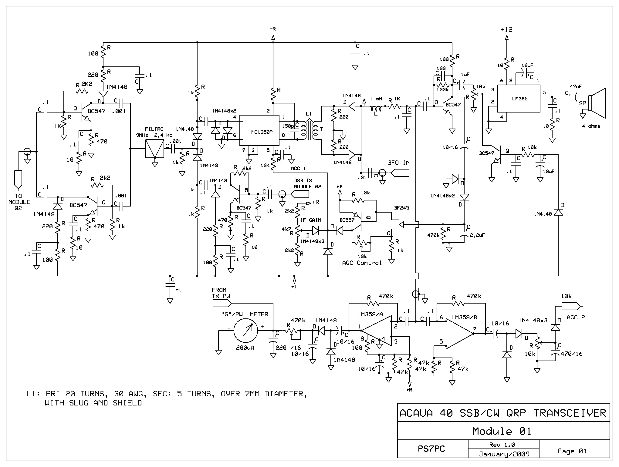
MODULE -01

Inicio da contagem de acessos a este artigo em 17/08/2013

![]()
![]()