The Toshiba 3.4 GHz 20W amplifiers
selling on E-bay recently use a high-density 15-pin Sub-D computer style
connector for power and control wiring. The HD Sub-D is something
of a bear to wire due to small pin sizes and close proximities inside the
shell. I have found that REPLACING the sub-D connector on the amplifier
is easy to do. It results in a much improved connection and gets
rid of the bulky computer connector sticking out the side.
On the original Sub-D connector, four pins
go to ground, four more go to +12VDC and several go to various control
functions on the main board. We only need the ground, +12VDC and
Pin 9 control lines connected. I used #14 red/black Zip-style power
cord for the power connections and a single #18 white wire for the Pin
9 extension. A small cover plate with grommet was fabricated to complete
the project.
1. Construct a small cover plate approximately
the size of the Sub-D connector flange (1/2 x 1-3/8). The screw
holes should be 1 apart and have clearance for a #6 screw. Drill
a hole in the center of the cover plate for the appropriate size rubber
grommet for the wires you are using. (I used #14 red/black power
cord and a #18 control wire. Slip about 6 of power cord and control
wire through the grommet so that it will go inside the amp case.
2. Remove the bottom plate. From the Sub-D connector, you will find that four ground wires (from pins 3, 7, 10 & 11) go to a 4-pin block connector. The +12VDC wires (from pins 1, 2, 12 & 12) pins go to another 4-pin block connector. The control wires (including Pin 9) go to a 7-pin block connector. This makes it convenient for rewiring.
3. Lift the three block connectors (noting which is 12VDC), remove the two threaded-socket screws securing the 15-pin Sub-D connector and carefully pull all the wires and connectors out through the opening.
4. Snip the four ground wires (pins 3,
7, 10 & 11) close to the Sub-D connector to maintain wire maximum length.
Strip about ¼ from the end of each and twist together. Strip
about 3/16 from the black #14 power lead. Use a short butt connector (I
made mine by cutting off the end of a ring connector.) to join the black
power lead and consolidated ground leads. Dont crimp; solder.
Insulate the solder joint with heat shrink tubing.
Note: I split the Zip power cord back about 2 and slid the heat-shrink down as far as possible before soldering the butt connector. I also used the jaws of a small Panavise as a heat sink to keep the tubing from shrinking before I got it into place.
5. Repeat the above procedure for the +12VDC connector block and red power lead.
6. Identify and tag Pin 9 before proceeding! Now, snip the wires from the 7-pin block and isolate all but the one that originally went to Pin 9. Join the Pin 9 wire to a length of #18 wire to bring the enable lead out. Use heat shrink to insulate this connection as well.
7. Put a piece of heat shrink over
the power cord and enable wire at the point where they exit the amplifier.
This will bundle everything together for easier handling and provide added
protection for the wires. It will also pull the split sections of
the Zip cord back together (remember how we got the heat shrink away from
the solder joint?).
1. Finally, run the wires through the grommet (a little WD-40 may help the process), slip the block connectors and wires through the hole in the side of the amp and use the two threaded-socket screws to secure the cover plate. Plug the connector blocks into the proper connectors and replace the bottom cover plate. Youre done!
Check the interior view (below) for a pictorial view of how to rewire the amp. The exterior view (below) shows the appearance of the connection from the outside.
Have fun on 3.4 GHz!
W7DHC
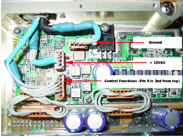 Amplifier - Interior View
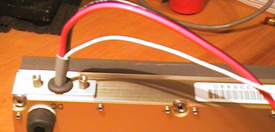 Amplifier - Exterior View
All materials on this site are copyrighted by their authors and/or the Pacific Northwest VHF Society. Unauthorized use is prohibited except as specifically stated. For permission to reproduce anything on this site please contact the society at [email protected].