Simple Stepper Driver


Lately someone dumped an old Star matrix printer on my desk. "You can take is or it'll go into the dumpster" was the accompanying remark. Of course I took it home and salvaged the stepper motors and driver IC's. The power supply looked usable also, so it went into the junkbox before throwing the remains into the dumpster. I had been toying with the idea to make an azimuth-elevation platform for a CCD camera for a while, so this could be the start. Now how was I supposed to drive the stepper motors? Of course there are enough stepper drivers available on the market, but my junk box is still full of logic chips, so why not design something simple? The spec called for a step and direction type interface. The original printer utilized a boost circuit which switched 24 volts to the motors only when they were supposed to move. The idling motors were connected to the 5 volts supply only, to prevent them to start smelling of current. Since there would be no real need for a high holding torque in my application, I decided to use the same approach. The advantage is obvious: we conserve power during standstill and when running the motors can develop more torque.  

steppercontrol

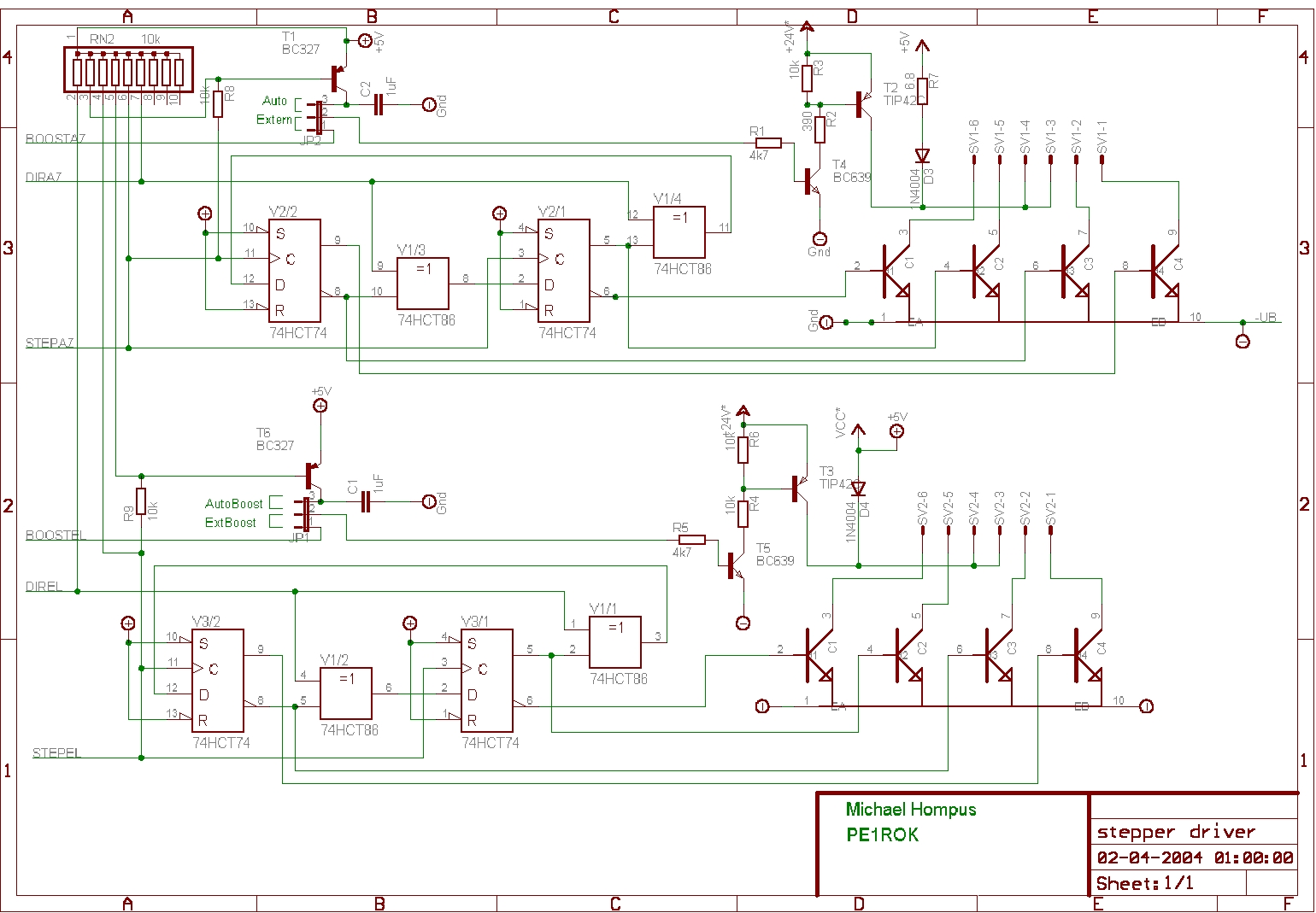
As you can see, I kept it simple. Only 3 chips are used to generate the pulse sequence for the coils of the 2 motors. The circuitry around the BOOST input might require some explanation. With the jumper the source of the boost signal can be selected. In the position external, raising the boost input causes the "high" voltage to be switched on. If the jumper is set to automatic, the 24 V is switched on by the falling edge of the PULSE input. In this case the controller should make a step by raising the PULSE input and leave it high. With the rising edge, the 24 V is switched on and the next output pattern is clocked into the '74 FlipFlops. After a short delay time (during which the motor makes the step, the 24 V is switched off again so the motor coils will not overheat. The transistors which I used came from the printer as well. The type numbers in the diagram just happened to correspond to usable parts in the component libraries of the layout saftware. Do not feel compelled to use the same. For the transistors in the main current path I suggest to use some PNP darlingtons. The other ones are small signal types. For the coil driver a ULN 2003 or similar would also be a good replacement if You do not have the original SanKen drivers.


Since a lot of information on driving stepper motors can be found on the internet, I will not explain the driving sequence for the motor coils in detail. A good source to start with is: "Jones on stepper motors" at http://www.cs.uiowa.edu/~jones/step/