| MF/HF
Wireless Telegraphy
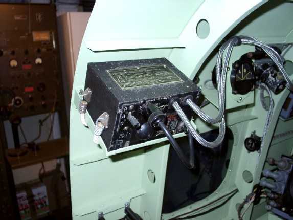
The wireless operator's transmitter and
receiver are mounted on the rear face of the radio panel, which is fitted
transversely across the table facing the wireless operator. The sets may
be connected to either the main fixed aerial on the starboard side or to
the trailing aerial, by means of the aerial plug board (early aircraft) or
the aerial switch (later aircraft). The winch for the trailing aerial,
together with a spare reel, is located on the port side below the table,
just forward the wireless operator's seat.
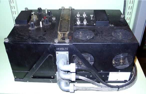
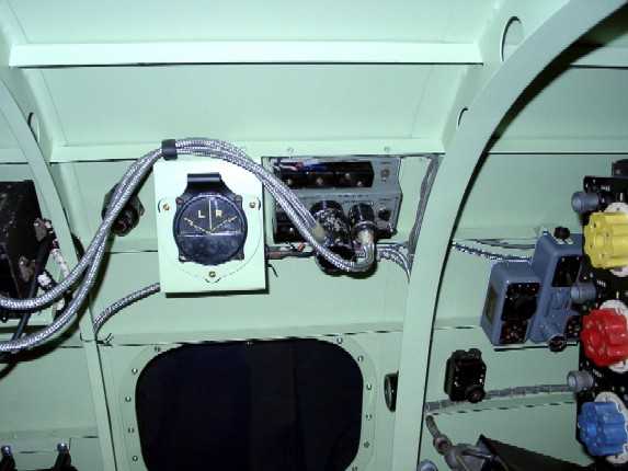
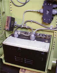
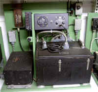
An HT power unit, type 33, an LT power unit, type 35A, and a relay type
220, are mounted on a stool on the main floor, centrally, beneath the
table.
|
 |
| Transmitter |
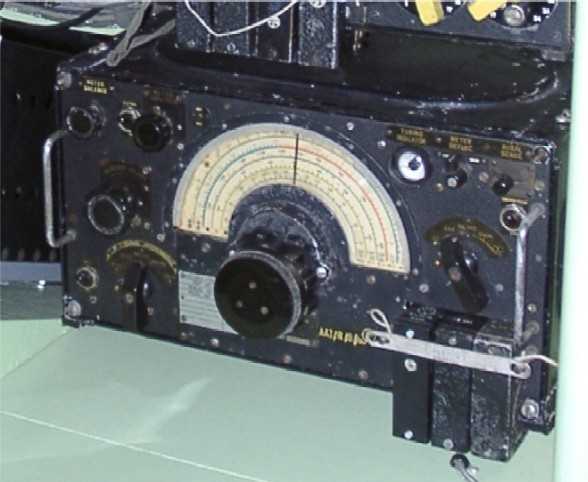
T1154 |
| Receiver |
R1155 |
| Purpose |
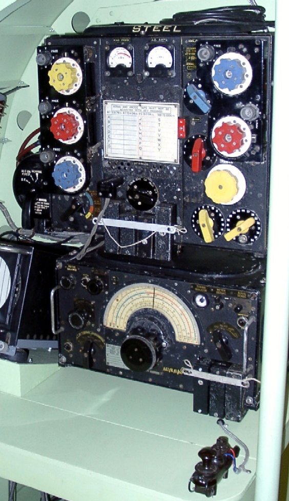
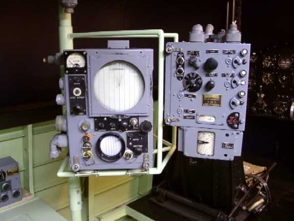
The standard radio
transmitter/receiver in all large aircraft of Bomber Common was the
transmitter T1154 and receiver R1155, which replaced the earlier
T1083/R1082. This radio installation is used for communication from air to
ground by W/T and R/T. |
| Type of wave |
T1154,
T1154B, T1154C, T1154D: R.T., M.C.W., C.W.
T1154A, T1154E: M.C.W., C.W.
R1155 C W., M.C.W. and R/T |
| Frequency range |
T
1154, T 1154A, T 1154B: 100 Mc/s-30 Mc/s and 500 kc/s - 200 kc/s in 3
ranges, BLUE (H.F.), RED (H.F.), VELLOW (M.F.)
T 1154C: 16,7 Mc/s - 2,35 Mc/s and 500 kc/s - 200 kc/s in 4 ranges. Two
BLUE (H.F.), RED (H.F.), YELLOW (M.F.)
T 1154D, T 1154E:
8 Mc/s 2,5
Mc/s and 500 kc/s - 200 kc/s in 3 ranges, BLUE (H.F.). RED (H.F.). YELLOW
(M.F.)
R115518
Mc/s. to 3 Mc/s. and 1.500 kc/s. to 75 kc/s. with gap between 600
kc/s. and 500 kc/s. In five
ranges. H.F. l8,5-7,5 Mc/s..
7,5-3,0 Mc/s. M.F. 1,500-600 kc/s., 500-200 kc/s. and 200-75 kc/s. |
| Transmitter Frequency stability |
Master-oscillator |
| Power input |
From
12V or 24V rotary transformer units
in conjunction with the aircraft general electrical supply. |
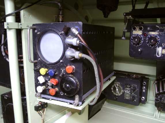
| HF
Radio Telephony (early aircraft)
This radio is on early aircraft mounted
on a stool on the floor below the navigator's table. Later is was
positioned in the rear fuselage.
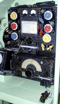
|
TR 1196
|
| Transmitter/Receiver |
Early: TR9, later TR1196 |
|
|
|
|
| Purpose |
For communication between aircraft, and the airfield control when returning to base the
aircraft was fitted with the TR9 or TR1196. |
| Type of wave |
R/T and M.C.W. |
| Frequency range |
4.3 Mc/s. to 6.7 Mc/s. in maximum of four 'spot"
frequency channels |
| Frequency stability |
Quartz crystal controlled |
| Power input |
Transmitter 250Volts, 60mA, HT; 6,3Volts, 1,3A;
heaters.
Receiver 275Volts, 35mA, HT;n6,3Volts, 1,2A; heaters. |
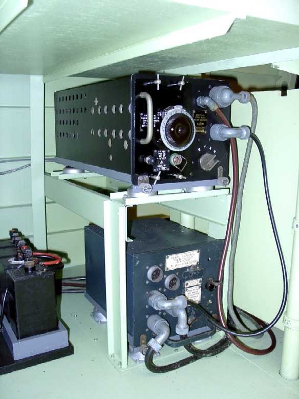
| VHF
Radio Telephony (later aircraft)
To improve the quality VHF radio's were
introduced, this radio is positioned in the rear fuselage.
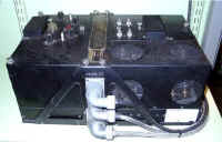
|
TR1143
TR5043
|
| Transmitter/Receiver |
TR1143 (mainly 5 group aircraft) or TR5043 (SCR-522) |
| Purpose |
For communication between aircraft, and the airfield control when returning to base the
aircraft was fitted with the TR1143 or TR5043 (US SCR-522). |
| Type of wave |
R/T and M.C.W. |
| Frequency range |
TR 1143: 100 to 124 Mc/s, in maximum of four 'spot"
frequency channels
TR 5043: 100 to 156 Mc/s. in maximum of four 'spot"
frequency channels |
| Frequency stability |
Quartz crystal controlled |
| Power input |
265 watts (receive). 295 watts (transmit) on 12 or 24 volts |
|
|
|
|
|
|
|
|
|
|